Server-based Migration to the Cloud Without Business Interruption (Direct Connect + Enterprise Switch)
Architecture
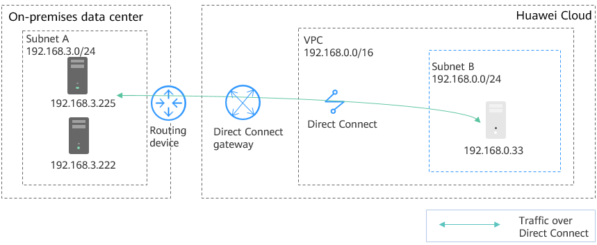
In Figure 1, the Subnet A in the on-premises data center connects to Subnet B on the cloud through Direct Connect. A customer wants to migrate some workloads in on-premises Subnet A to the cloud. The requirements are as follows:
- Servers migrated to the cloud can communicate with on-premises servers at Layer 2 even if their subnets are the same.
- The Layer 2 network extended to the cloud can communicate with the on-premises data center at Layer 3.
- The Layer 2 network reconstructed at the on-premises data center can communicate with the cloud at Layer 3.
The network deployment details are as follows:
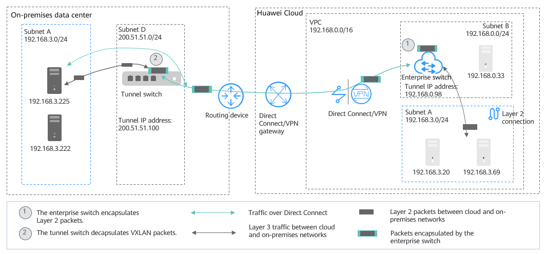
- Migrate Subnet A to the cloud at Layer 2. Use an enterprise switch to allow the cloud Subnet A and the on-premises Subnet A to communicate at Layer 2. Figure 2 shows the networking diagram.
- Create Subnet D in the on-premises data center as the tunnel subnet required by the on-premises VXLAN switch.
- Create Subnet A in the VPC on the cloud and use it as the one that is migrated from the on-premises Subnet A.
- Use the Subnet B on the cloud as the tunnel subnet, create an enterprise switch and a Layer 2 connection in the subnet, and associate the subnet with a Direct Connect connection to allow cloud and on-premises networks to communicate at Layer 2.
- Create a Subnet C both on the cloud and in the on-premises data center. Use an enterprise switch to allow the two subnets to communicate at Layer 2. Use Direct Connect to allow Layer 3 communication between on-premises Subnet A and cloud Subnet C, and between cloud Subnet A and on-premises Subnet C. Figure 3 shows the networking diagram.
- Create a Subnet C both on the cloud and in the on-premises data center.
- Create a Layer 2 connection based on the existing tunnel subnets to connect the cloud Subnet C and on-premises Subnet C at Layer 2.
Subnets in the same VPC communicate at Layer 3. On-premises Subnet A and cloud Subnet C, cloud Subnet A and on-premises Subnet C communicate at Layer 3.
Resource and Cost Planning
|
Region |
Resource |
Description |
Quantity |
|---|---|---|---|
|
Huawei Cloud |
Subnet |
Name: Subnet A CIDR block: 192.168.3.0/24 Subnet of the Layer 2 connection A. This is the subnet that the cloud ECSs reside. |
3 |
|
Name: Subnet C CIDR block: 192.168.5.0/24 Subnet of the Layer 2 connection C. This is the subnet that the cloud ECSs reside. |
|||
|
Name: Subnet B CIDR block: 192.168.0.0/24 This is the tunnel subnet on Huawei Cloud, used by the Direct Connect connection and the enterprise switch. |
|||
|
ECS |
|
4 |
|
|
Enterprise switch |
|
1 |
|
|
Layer 2 connection |
Layer 2 connections of the same enterprise switch must have the same tunnel IP address, but different tunnel VNIs. |
2 |
|
|
On-premises data center |
Subnet |
Name: Subnet A CIDR block: 192.168.3.0/24 Subnet of the Layer 2 connection A. This is the subnet that the on-premises clusters reside. |
3 |
|
Name: Subnet C CIDR block: 192.168.5.0/24 Subnet of the Layer 2 connection C. This is the subnet that the on-premises clusters reside. |
|||
|
Name: Subnet D CIDR block: 200.51.51.0/24 Tunnel subnet in the on-premises data center |
|||
|
VXLAN tunnel corresponding to Layer 2 connection |
|
2 |
Migration Process
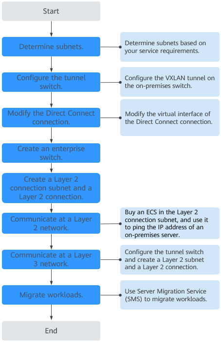
- Plan resources and networks based on actual requirements.
For details, see Table 1.

- The subnets shown in the examples are for demonstration purposes. Adjust them according to actual subnets.
- Do not set the tunnel subnet too large. The tunnel IP address is assigned from this tunnel subnet to establish a VXLAN tunnel with the enterprise switch on Huawei Cloud. For details, see Figure 2.
- Configure the VXLAN tunnel on the on-premises tunnel switch.
In this example, Subnet D is used by the tunnel switch.
- Source address: On-premises tunnel IP address (200.51.51.100)
- Destination address: Tunnel IP address on the cloud (192.168.0.98)
- Tunnel VNI: 5530
For details about how to configure on-premises switches, see Configuring a Tunnel Gateway in Your Data Center.
- Modify the virtual interface of the Direct Connect connection and associate Subnet D (200.51.51.0/24) with the connection to enable the communication between the cloud and on-premises tunnel subnets.
For details, see Modifying a Virtual Interface.
- Submit a service ticket to check whether your Direct Connect connection supports VXLAN interconnection with an enterprise switch. If your connection does not support this, contact the Direct Connect service to enable the interconnection.
- Buy an enterprise switch.
For details, see Buying an Enterprise Switch.
- Tunnel Connection: Select Direct Connect.
- Connection Gateway: Select an existing Direct Connect gateway.
- Tunnel Subnet: Select Subnet B (192.168.0.0/24).
- Tunnel IP Address: Set it to the tunnel IP address (192.168.0.98) on the cloud.
Click Next and then Submit. This operation takes 3 to 6 minutes to complete.
- Create a Layer 2 connection subnet and Layer 2 connection to allow cloud Subnet A and on-premises Subnet A to communicate at Layer 2.

After a Layer 2 connection subnet is created, the cloud and on-premises subnets have the same CIDR block. As a result, there are conflicting routes used to forward traffic over the Direct Connect connection at Layer 3. Communication at Layer 3 over the connection will be restored only after Layer 2 connections are created.
- Create a Layer 2 connection subnet (Subnet A: 192.168.3.0/24) in the VPC.
For details about how to create a subnet, see Creating a Subnet for the VPC.

- Subnet A, Subnet B, Subnet C and Subnet D cannot overlap.
- Subnet D is used as the tunnel subnet. Set its netmask to 28.
- The CIDR block of the VPC on the cloud depends on the number of required enterprise switches. Each enterprise switch needs three IP addresses from the tunnel subnet.
- Create a Layer 2 connection A between cloud Subnet A and on-premises Subnet A.
For details, see Creating a Layer 2 Connection.
- Layer 2 connection subnet: Subnet A (192.168.3.0/24) on the cloud
- Remote Access Information
- Tunnel VNI: 5530
- Tunnel IP address: 200.51.51.100
- Click Create. If the connection status changes to Connected, the Layer 2 connection is created successfully.
- Create a Layer 2 connection subnet (Subnet A: 192.168.3.0/24) in the VPC.
- Check communication between cloud Subnet A and on-premises Subnet A at Layer 2.
- Create two ECSs in the Layer 2 connection subnet (Subnet A) on the cloud.
The private IP addresses of the two ECSs are 192.168.3.20 and 192.168.3.69, respectively.
- Log in to the two ECSs.
Multiple methods are available for logging in to an ECS. For details, see Logging In to an ECS.
In this example, use VNC provided on the management console to log in to an ECS.
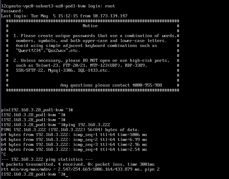
- Check whether the ECSs can communicate with on-premises servers.
ping IP address of an on-premises server in the on-premises Subnet A
Example commands:
- ping 192.168.3.255
- ping 192.168.3.222
If information similar to the following is displayed, the cloud and on-premises subnets can communicate at Layer 2.
- Create two ECSs in the Layer 2 connection subnet (Subnet A) on the cloud.
- Create a Layer 2 connection subnet and a Layer 2 connection to allow on-premises and cloud subnets to communicate at Layer 3.
- Create a Layer 2 connection subnet (Subnet C: 192.168.5.0/24) in the VPC.
For details about how to create a subnet, see Creating a Subnet for the VPC.
- Create a Layer 2 connection C between cloud Subnet C and on-premises Subnet C.
For details, see Creating a Layer 2 Connection.
- Layer 2 connection subnet: Subnet C (192.168.5.0/24) on the cloud
- Remote Access Information
- Tunnel VNI: 5540
- Tunnel IP address: 200.51.51.100
- Click Create. If the connection status changes to Connected, the Layer 2 connection is created successfully. In this case, cloud and on-premises subnets can communicate with each other at Layer 3.
- Refer to 7 to check the communication between cloud Subnet C and on-premises Subnet C at Layer 2.
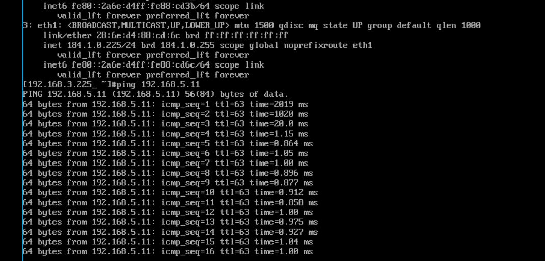
- Refer to 7 to check the communication between on-premises Subnet A and cloud Subnet C, and between on-premises Subnet A and cloud Subnet C at Layer 3.
If information similar to the following is displayed, the subnets can communicate with each other at Layer 3.
- Create a Layer 2 connection subnet (Subnet C: 192.168.5.0/24) in the VPC.
- Migrate the workloads to the cloud.
- Migrate on-premises workloads to the cloud at Layer 2.
For details, see Server Migration Service Quick Start.
- Check the network communication between cloud and on-premises servers.
- If the communication is normal, stop the on-premises servers that their workloads are migrated to the cloud.
- Change the IP address of servers on the cloud to the IP address of the servers in the on-premises data center.
For details, see Modifying a Private IP Address.
- Check the network communication between cloud and on-premises servers.
- Migrate on-premises workloads to the cloud at Layer 2.
FAQs
If the subnets to be connected at Layer 2 are not on the same network, the VPC of the enterprise switch must have different CIDR blocks. In this case, you need to use a tool to create subnets across CIDR blocks. If you need help, submit a service ticket.
Feedback
Was this page helpful?
Provide feedbackThank you very much for your feedback. We will continue working to improve the documentation.See the reply and handling status in My Cloud VOC.
For any further questions, feel free to contact us through the chatbot.
Chatbot

