
Using a Central Network and Enterprise Routers to Connect VPCs in the Same Account But Different Regions
Relying on the Huawei backbone network, you can set up a central network to manage global network resources on premises and on the cloud easily and securely. After attaching the VPCs to enterprise routers in each region, you can add the enterprise routers to a central network, so that all the VPCs attached to the enterprise routers can communicate with each other across regions.
In this topic, a central network and enterprise routers are used to connect the VPCs in the same account but different regions.

- For details about the regions where central networks are available, see Region Availability.
- The CIDR blocks of the VPCs must be unique. If there are overlapping CIDR blocks, the communication may fail.
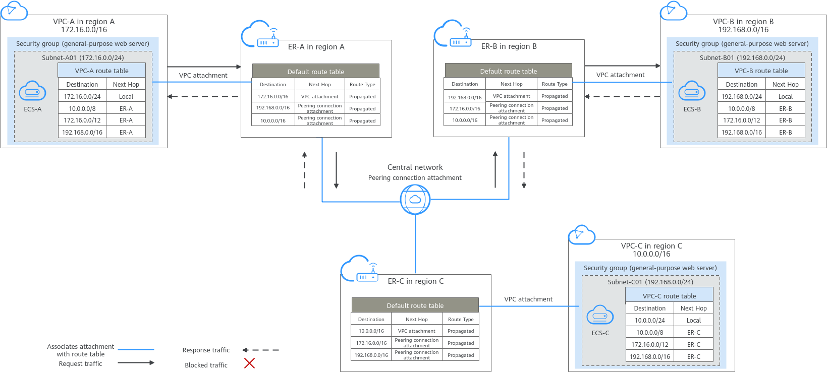
Architecture
- Create an enterprise router in each region: ER-A in region A, ER-B in region B, and ER-C in region C.
- Create a central network and add ER-A, ER-B, and ER-C to the central network as attachments so that the three enterprise routers can communicate with each other.
- In region A, attach VPC-A01 and VPC-A02 to ER-A so that the two VPCs can communicate with each other. Perform the same operations in regions B and C. In this way, the VPCs in the three regions can communicate with each other over the central network.

You can share an enterprise router with different accounts to attach VPCs of these accounts to the same enterprise router for communications.
Network and Resource Planning
- Plan the central network, VPCs and their subnets, VPC route tables, and enterprise router route tables.
- Plan the quantities, names, and main parameters of cloud resources, including central network, enterprise router, VPC, and ECS.
Network Planning
Figure 2 shows the network planning for communication between VPCs across regions. For details about the network planning, see Table 2.
In this example, one VPC is created and attached to an enterprise router in each region. Make the plan based on your service requirements.
| Traffic Flow | What to Do |
|---|---|
| Request traffic: from VPC-A to VPC-B |
|
| Response traffic: from VPC-B to VPC-A |
|
| Resource | Description |
|---|---|
| VPC |
|
| Central network |
|
| Enterprise router | The network configuration for the enterprise router in the three regions is the same. Table 4 lists all routes required by the enterprise router. When a central network is set up to connect the enterprise routers, you must enable Default Route Table Association and Default Route Table Propagation for the enterprise routers. In this way, when an instance is added to an enterprise router, a route pointing to the attachment will be automatically added for the enterprise router. |
| ECS | An ECS is created in each VPC. If the ECSs are in different security groups, add rules to the security groups to allow access to each other. |
| Destination | Next Hop | Route Type |
|---|---|---|
| 10.0.0.0/8 | Enterprise router | Static route (custom) |
| 172.16.0.0/12 | Enterprise router | Static route (custom) |
| 192.168.0.0/16 | Enterprise router | Static route (custom) |
- If you enable Auto Add Routes when creating a VPC attachment, you do not need to manually add static routes to the VPC route table. Instead, the system automatically adds routes (with this enterprise router as the next hop and 10.0.0.0/8, 172.16.0.0/12, and 192.168.0.0/16 as the destinations) to all route tables of the VPC.
- If an existing route in the VPC route tables has a destination to 10.0.0.0/8, 172.16.0.0/12, or 192.168.0.0/16, the routes will fail to be added. In this case, do not enable Auto Add Routes. After the attachment is created, manually add routes.
- Do not set the destination of a route (with an enterprise router as the next hop) to 0.0.0.0/0 in the VPC route table. If an ECS in the VPC has an EIP bound, the VPC route table will have a policy-based route with 0.0.0.0/0 as the destination, which has a higher priority than the route with the enterprise router as the next hop. In this case, traffic is forwarded to the EIP and cannot reach the enterprise router.
| Enterprise router | Destination | Next Hop | Route Type |
|---|---|---|---|
| Region A: ER-A | VPC-A CIDR block: 172.16.0.0/16 | VPC-A attachment: er-attach-VPC-A | Propagated route |
| VPC-B CIDR block: 192.168.0.0/16 | Peering connection attachment: region-A-region-B | Propagated route | |
| VPC-C CIDR block: 10.0.0.0/16 | Peering connection attachment: region-A-region-C | Propagated route | |
| Region B: ER-B | VPC-B CIDR block: 192.168.0.0/16 | VPC-B attachment: er-attach-VPC-B | Propagated route |
| VPC-A CIDR block: 172.16.0.0/16 | Peering connection attachment: region-B-region-A | Propagated route | |
| VPC-C CIDR block: 10.0.0.0/16 | Peering connection attachment: region-B-region-C | Propagated route | |
| Region C: ER-C | VPC-C CIDR block: 10.0.0.0/16 | VPC-C attachment: er-attach-VPC-C | Propagated route |
| VPC-A CIDR block: 172.16.0.0/16 | Peering connection attachment: region-C-region-A | Propagated route | |
| VPC-B CIDR block: 192.168.0.0/16 | Peering connection attachment: region-C-region-B | Propagated route |
Resource Planning
The following resource planning is only for your reference.
| Resource | Quantity | Description |
|---|---|---|
| VPC | 3 | A service VPC is required in each region for running workloads. Each VPC needs to be attached to an enterprise router in the same region.
|
| Enterprise router | 3 | An enterprise router is required in each region. The VPC in each region is attached to the corresponding enterprise router, and a peering connection attachment is created between every two enterprise routers.
|
| Central network | 1 | A central network is required, and all enterprise routers are added to it as attachments.
|
| Global connection bandwidth | 3 | Three global connection bandwidths are required to connect the cloud backbone networks in different regions.
|
| ECS | 3 | Create an ECS in each VPC to verify network connectivity.
|
Process
| Step | What to Do |
|---|---|
| Before using cloud services, sign up for a HUAWEI ID, enable Huawei Cloud services, complete real-name authentication, and top up your account. | |
| |
| Create a VPC attachment to each enterprise router. | |
| Step 3: Assign Cross-Site Connection Bandwidths for the Central Network | Assign cross-site connection bandwidths on the central network based on service requirements. |
| Log in to an ECS and run the ping command to verify the network connectivity. |
Preparations
Before creating a cloud connection, you need to sign up for a HUAWEI ID, enable Huawei Cloud services, complete real-name authentication, and top up your account. Ensure that your account has sufficient balance.
- Sign up for a HUAWEI ID, enable Huawei Cloud services, and complete real-name authentication.
- Top up your account.
Ensure that your account has sufficient balance. For details about how to top up an account, see Topping up an Account.
Step 1: Create Cloud Resources
In this example, you need to create a central network, three enterprise routers, three VPCs, and three ECSs based on Table 5.
- Create an enterprise router in each of the three regions.
For details, see Creating an Enterprise Router.
Specify a unique ASN for each enterprise router.
- Create a VPC in each of the three regions.
For details, see Creating a VPC with a Subnet.
- Create an ECS in each of the three regions.
For details, see Purchasing an ECS in Custom Config Mode.
- Create a central network and add the enterprise routers to the central network as attachments.
- Create a central network and add the enterprise routers to the central network as attachments.
For details, see Creating a Central Network.
- On the Enterprise Router console, view the peering connection attachments.
For details, see Viewing Details About an Attachment.
If the status of the peering connection attachments is Normal, the attachments are available.
Default Route Table Association and Default Route Table Propagation are enabled when you create enterprise routers. After peering connection attachments are created for the enterprise routers, Enterprise Router will automatically:- Associate the peering connection attachment with the default route table of each enterprise router.
- Propagate the peering connection attachment to the default route table of each enterprise router. The route tables automatically learn routes from each other.
- Create a central network and add the enterprise routers to the central network as attachments.
- Purchase three global connection bandwidths to connect networks in different regions.
For details, see Purchasing a Global Connection Bandwidth.
Step 2: Create a VPC Attachment for Each Enterprise Router
Create a VPC attachment for each enterprise router. For details about resource planning, see Table 5.
- In region A, attach VPC-A to enterprise router ER-A.
- Attach the VPC to the enterprise router.
In this example, enable Auto Add Routes to save you from manually configuring routes in the VPC route table.
For details, see Creating VPC Attachments for an Enterprise Router.
Default Route Table Association and Default Route Table Propagation are enabled when you create the enterprise router. After VPCs are attached to the enterprise routers, Enterprise Router will automatically:- Associate the VPC attachments with the default route table of the enterprise router.
- Propagate the VPC attachments to the default route table of the enterprise router. The route table automatically learns the VPC CIDR blocks as the destination of routes.
- (Optional) Add routes to the VPC route table for traffic to route through the enterprise router.
Skip this step if you have enabled Auto Add Routes in the previous step. For details about routes, see Table 3.
For details, see Adding Routes to VPC Route Tables.
- Attach the VPC to the enterprise router.
- In region B, attach VPC-B to enterprise router ER-B by referring to 1.
- In region C, attach VPC-C to enterprise router ER-C by referring to 1.
Step 3: Assign Cross-Site Connection Bandwidths for the Central Network
To allow cross-region VPC communications, you need to assign cross-region connection bandwidths on the central network based on service requirements by referring to Table 5.
By default, Cloud Connect allocates 10 kbit/s of bandwidth for testing connectivity between regions. After the peering connection attachments are created, you can verify the network connectivity between VPCs. For details, see Step 4: Verify Network Connectivity.
To ensure your workloads run normally, you need to purchase global connection bandwidths and assign cross-site connection bandwidths.
- Assign a cross-site connection bandwidth from the purchased global connection bandwidth for the communication between region A and region B.
For details, see Assigning a Cross-Site Connection Bandwidth.
- Assign a cross-site connection bandwidth from the purchased global connection bandwidth for the communication between region A and region C.
- Assign a cross-site connection bandwidth from the purchased global connection bandwidth for the communication between region B and region C
Step 4: Verify Network Connectivity
- Log in to an ECS.
Multiple methods are available for logging in to an ECS. For details, see Logging In to an ECS.
In this example, use VNC provided on the management console to log in to an ECS.
- In the remote login window of the ECSs, use ping to verify the network connectivity:
- Verify the network connectivity between two VPCs.
ping <private-IP-address-of-the-ECS>
Log in to ECS-A to verify the network connectivity between VPC-A and VPC-B:
ping 192.168.0.5
If information similar to the following is displayed, VPC-A and VPC-B can communicate with each other normally:[root@ECS-A ~]# ping 192.168.0.5 PING 192.168.0.5 (192.168.0.5) 56(84) bytes of data. 64 bytes from 192.168.0.5: icmp_seq=1 ttl=62 time=30.6 ms 64 bytes from 192.168.0.5: icmp_seq=2 ttl=62 time=30.2 ms 64 bytes from 192.168.0.5: icmp_seq=3 ttl=62 time=30.1 ms 64 bytes from 192.168.0.5: icmp_seq=4 ttl=62 time=30.1 ms ... --- 192.168.0.5 ping statistics ---
- Verify the network connectivity between another two VPCs.
ping <private-IP-address-of-the-ECS>
Log in to ECS-A to verify the network connectivity between VPC-A and VPC-C:
ping 10.0.0.29
If information similar to the following is displayed, VPC-A and VPC-C can communicate with each other normally:[root@ECS-A ~]# ping 10.0.0.29 PING 10.0.0.29 (10.0.0.29) 56(84) bytes of data. 64 bytes from 10.0.0.29: icmp_seq=1 ttl=62 time=27.4 ms 64 bytes from 10.0.0.29: icmp_seq=2 ttl=62 time=27.0 ms 64 bytes from 10.0.0.29: icmp_seq=3 ttl=62 time=26.10 ms 64 bytes from 10.0.0.29: icmp_seq=4 ttl=62 time=26.9 ms ... --- 10.0.0.29 ping statistics ---
- Verify the network connectivity between two VPCs.
- Repeat 1 and 2 to verify the network connectivity between VPC-B and VPC-C.
Feedback
Was this page helpful?
Provide feedbackThank you very much for your feedback. We will continue working to improve the documentation.See the reply and handling status in My Cloud VOC.
For any further questions, feel free to contact us through the chatbot.
Chatbot


