Using a Cloud Connection and a VPC Peering Connection to Connect VPCs Across Regions
Scenarios
This practice provides detailed operations for you to enable communication between VPCs in different regions using a VPC Peering connection and a cloud connection.
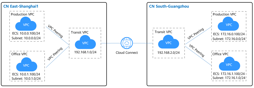
In the following figure, CN East-Shanghai1 and CN South-Guangzhou each have three VPCs, one production VPC, one office VPC, and one transit VPC:
- The production VPC in CN East-Shanghai1 needs to communicate with the production VPC in CN South-Guangzhou.
- The office VPC in CN East-Shanghai1 needs to communicate with the office VPC in CN South-Guangzhou.
- The production VPC and the office VPC cannot communicate with each other.
|
Cloud Service |
Scenario |
Description |
Related Operations |
|---|---|---|---|
|
VPC Peering |
Two VPCs are in the same region. |
Create a VPC peering connection to connect two VPCs in the same region. The two VPCs can be in the same account or in different accounts. |
Creating a VPC Peering Connection to Connect Another VPC in the Same Account Creating a VPC Peering Connection to Connect a VPC in Another Account |
|
Cloud connection |
VPCs are in different regions. |
Create a cloud connection to connect the VPCs across regions. The VPCs can be in the same account or in different accounts. |
Using a Cloud Connection to Connect VPCs in Different Regions |

To connect the VPCs using a VPC Peering connection and a cloud connection, ensure that the subnets in the VPCs do not overlap or conflict.
Prerequisites
- You have a Huawei Cloud account, and the Huawei Cloud account has been configured with operation permissions of related services.
- The account balance is sufficient to purchase the required resources, such as bandwidth packages and ECSs.
- The VPCs and subnets that need to communicate with each other have been created.
Procedure
- Configure VPC Peering.
- Create a VPC peering connection.
- Go to the VPC Peering Connections page.
- In the upper right corner of the page, click Create VPC Peering Connection.
The Create VPC Peering Connection page is displayed.
- Configure the parameters based on Table 2. Select My account.
Figure 2 Creating a VPC peering connection
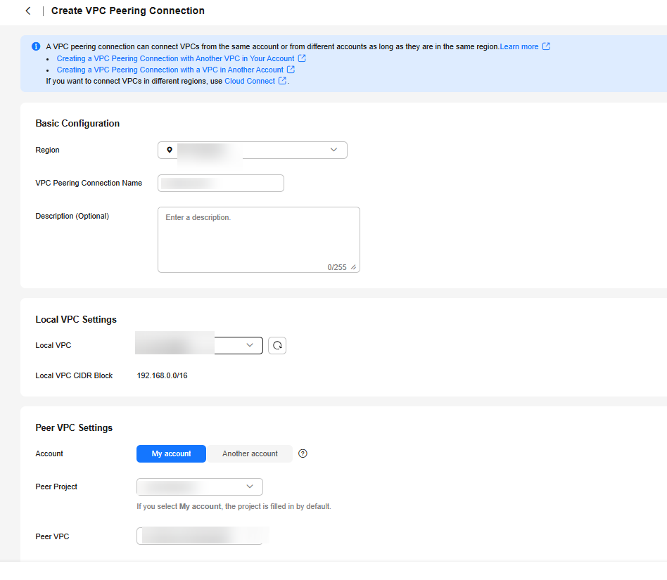
Table 2 Parameters required for creating a VPC peering connection Parameter
Description
Example Value
Region
Mandatory
Region where the VPC peering connection will be created. Select the region nearest to you to ensure the lowest latency possible.
CN East-Shanghai1
VPC Peering Connection Name
Mandatory
Name of the VPC peering connection.
The name contains a maximum of 64 characters and consists of letters, digits, hyphens (-), and underscores (_).
Production VPC peering in CN East-Shanghai1
Description (Optional)
Optional.
The supplementary information about the VPC peering connection.
The description can contain no more than 255 characters and cannot contain angle brackets (<>).
-
Local VPC
Mandatory
VPC at one end of the VPC peering connection. You can select one from the drop-down list.
Transit VPC in CN East-Shanghai1
Local VPC CIDR Block
CIDR block of the selected local VPC.
192.168.0.0/16
Account
Mandatory- My account: The local and peer VPCs are from the same account.
- Another account: The local and peer VPCs are from different accounts.
My account
Peer Project
The system fills in the corresponding project by default if Account is set to My account.
For example, if VPC-A and VPC-B are created in region A, the corresponding project of the account in region A is selected by default.
cn-east-3
Peer VPC
This parameter is mandatory if Account is set to My account.
VPC at the other end of the VPC peering connection. You can select one from the drop-down list.
Production service VPC in CN East-Shanghai1
Peer VPC CIDR Block
Specifies the CIDR block for the peer VPC.
The local and peer VPCs cannot have identical or overlapping CIDR blocks. Otherwise, the routes added for the VPC peering connection may not take effect.
172.16.0.0/12
- Click Create Now.
- Add routes for the VPC peering connection.
If you request a VPC peering connection with another VPC in your own account, the system automatically accepts the request. You still need to add local and peer routes on the Route Tables page for the VPC peering connection.
- Go to the VPC console.
- In the navigation pane on the left, choose Route Tables.
- Search for or create a route table for the local VPC and add routes for the local VPC. Table 3 describes the parameters.
Figure 3 Adding local route
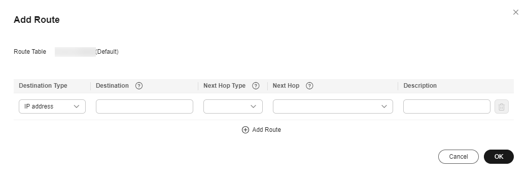
Table 3 Parameters required for adding routes for the VPC peering connection Parameter
Description
Example Value
Destination
Specifies the CIDR block for the peer VPC.
172.16.0.0/12
Next Hop Type
Specifies the next hop type. Select VPC peering connection.
VPC peering connection
Next Hop
Specifies the next hop address. Select the created VPC peering connection.
Production VPC peering in Shanghai1
Description
(Optional) Provides supplementary information about the route.
The description can contain no more than 255 characters and cannot contain angle brackets (<>).
-
- Search for or create a route table for the peer VPC and add routes for the peer VPC.
Table 4 Parameters required for adding routes for the VPC peering connection Parameter
Description
Example Value
Destination
Specifies the CIDR block for the local VPC.
192.168.0.0/16
Next Hop Type
Specifies the next hop type. Select VPC peering connection.
VPC peering connection
Next Hop
Specifies the next hop address. Select the created VPC peering connection.
Production VPC peering in CN East-Shanghai1
Description
(Optional) Provides supplementary information about the route.
The description can contain no more than 255 characters and cannot contain angle brackets (<>).
-
- Repeat the above steps to create a VPC peering connection between the office VPC and the transit VPC in CN East-Shanghai1 and add local and peer routes.

Repeat the above operations to create two VPC peering connections in CN South-Guangzhou, with one connecting the production VPC to the transit VPC and the other connecting the office VPC to the transit VPC.
In the above steps, you can visit the route table module directly from the navigation pane on the left.
- Create a VPC peering connection.
- Create a cloud connection.
- Create a cloud connection.
- Go to the Cloud Connections page.
- In the upper right corner of the page, click Create Cloud Connection.
- Configure the parameters based on Table 5.
Figure 4 Creating a cloud connection
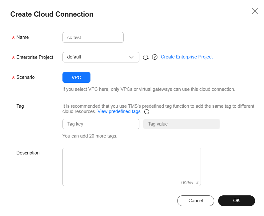
Table 5 Parameters for creating a cloud connection Parameter
Description
Example Value
Name
Specifies the cloud connection name.
The name can contain 1 to 64 characters. Only letters, digits, underscores (_), hyphens (-), and periods (.) are allowed.
cc-test
Enterprise Project
Specifies an enterprise project by which cloud resources and members are centrally managed.
default
Scenario
VPC: Only VPCs or virtual gateways can use this cloud connection.
VPC
Tag
Specifies the tag to identify the cloud connection. A tag consists of a key and a value. You can add up to 20 tags to a cloud connection.
NOTE:If a predefined tag has been created on TMS, you can directly select the corresponding tag key and value.
For details about predefined tags, see Predefined Tags.
-
Description
Provides supplementary information about the cloud connection.
The description can contain no more than 255 characters.
-
- Click OK.
- Load network instances.
Load the transit VPC in CN East-Shanghai1 to the created cloud connection.
- In the cloud connection list, click the name (cc-test) of the cloud connection.
- Select the Network Instances tab and click Load Network Instance.
- Configure the parameters.
Figure 5 Network instance details
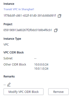

To communicate with the production VPC and the office VPC in CN East-Shanghai1, you need to set the CIDR blocks of the two VPCs as custom CIDR blocks.
- Click OK.
- Repeat the above steps to load the transit VPC in CN South-Guangzhou to the cloud connection and set the CIDR block of the production VPC and the CIDR block of the office VPC in CN South-Guangzhou as custom CIDR blocks.
Figure 6 Loading another VPC
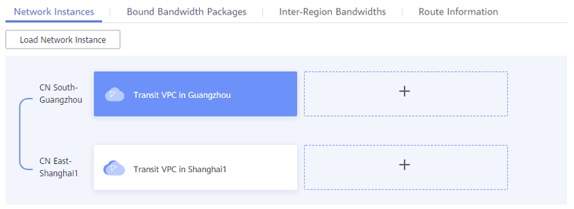

After the VPCs are loaded, they are on the same network. You can view the routes of each VPC on the Route Information tab.
- Buy a bandwidth package.
By default, Cloud Connect provides 10 kbit/s of bandwidth for testing cross-region network connectivity.
To ensure normal communication, you need to purchase a bandwidth package and bind it to the cloud connection.
- In the cloud connection list, click the name (cc-test) of the cloud connection.
- On the Bandwidth Packages tab, click Buy Bandwidth Package.
- Configure the parameters.
Because the two VPCs are in the Chinese mainland, select Single geographic region for Applicability and Chinese mainland for Geographic Region.
- Click Next.
- Confirm the configuration and submit your order.
Go back to the bandwidth package list and locate the bandwidth package. If its status changes to Normal, you can bind the bandwidth package to the cloud connection.

In the navigation pane, choose Bandwidth Packages. On the Bandwidth Packages package, you can view the purchased bandwidth package and its details, such as the billing mode, order information, the cloud connection, used bandwidth, and remaining bandwidth. You can also modify, unbind, renew, and unsubscribe from the bandwidth package.
- Assign an inter-region bandwidth.
Assign bandwidth from the purchased bandwidth package for communication between the VPCs.
- In the cloud connection list, click the name (cc-test) of the cloud connection.
- On the Inter-Region Bandwidths tab, click Assign Inter-Region Bandwidth.
- Configure the parameters.
Select CN South-Guangzhou and CN East-Shanghai1 for Regions. The system automatically displays the bandwidth package bound to the cloud connection. Set the bandwidth based on your requirements, for example, 1 Mbit/s.
- View the assigned bandwidth on the Inter-Region Bandwidths tab.
- Create a cloud connection.
Verification
- Check the route table of the transit VPC in CN East-Shanghai1.
Figure 7 Route table of the transit VPC in CN East-Shanghai1

- Check the route table of the production VPC in CN East-Shanghai1.
Figure 8 Route table of the production VPC in CN East-Shanghai1

- Check the route table of the office VPC in CN East-Shanghai1.
Figure 9 Route table of the office VPC in CN East-Shanghai1

- Check the route table of the transit VPC in CN South-Guangzhou.
Figure 10 Route table of the transit VPC in CN South-Guangzhou

- Check the route table of the production VPC in CN South-Guangzhou.
Figure 11 Route table of the production VPC in CN South-Guangzhou

- Check the route table of the office VPC in CN South-Guangzhou.
Figure 12 Route table of the office VPC in CN South-Guangzhou

- Ping an ECS in the production VPC in CN South-Guangzhou from an ECS in the production VPC in CN East-Shanghai1.
Figure 13 Pinging two ECSs
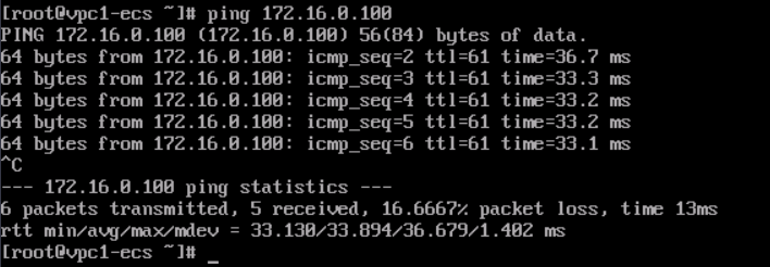
- Ping an ECS in the office VPC in CN South-Guangzhou from an ECS in the office VPC in CN East-Shanghai1.
Figure 14 Pinging two ECSs

Feedback
Was this page helpful?
Provide feedbackThank you very much for your feedback. We will continue working to improve the documentation.See the reply and handling status in My Cloud VOC.
For any further questions, feel free to contact us through the chatbot.
Chatbot


