
Designing an Technical Architecture on InnoStage Workbench
This section describes how to use the InnoStage Workbench Design Center to meet architects' architecture design requirements.
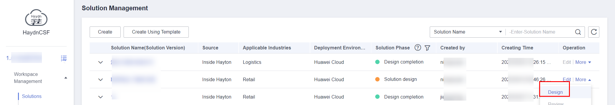
Architecture design entry
- After the solution is registered, locate it, choose [More] > [Design] in the Operation column to go to the solution design page,the architecture diagram belongs to the solution in the workspace.
Figure 1

- Click [Quick Architecture Design] on the Innostage homepage,directly access the design center for architecture design,the architecture diagram is not in any workspace and can only be viewed and manipulated by you.
Figure 2 Going to the solution design page
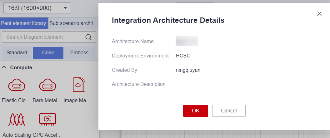
- Create an technical architecture.Click [Create Technical Architecture], select the architecture type, click the technical architecture diagram, enter the architecture name, select the architecture template, and select the deployment environment.
Figure 3 New Integration Architecture
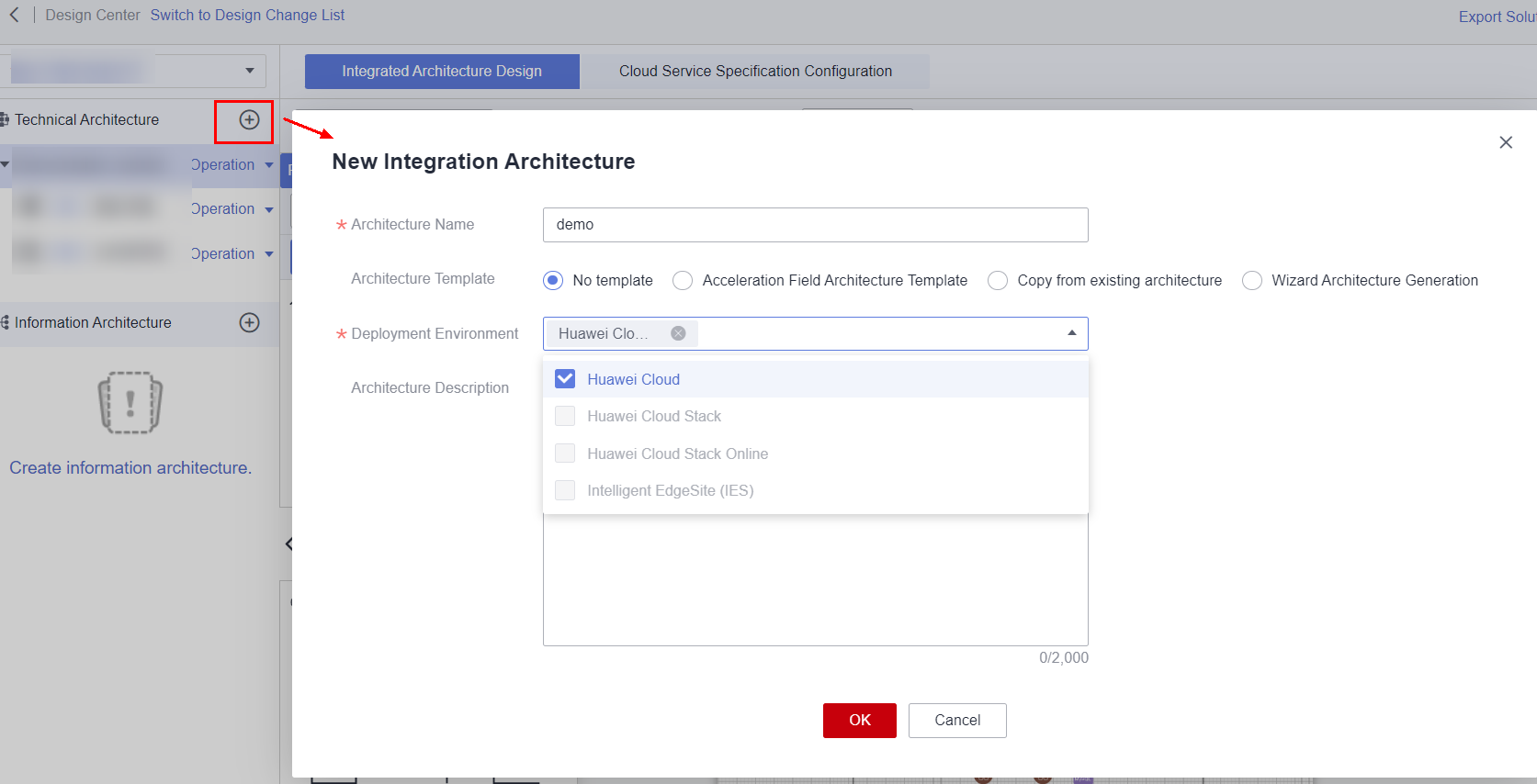 Figure 4 Layout of the technical architecture design
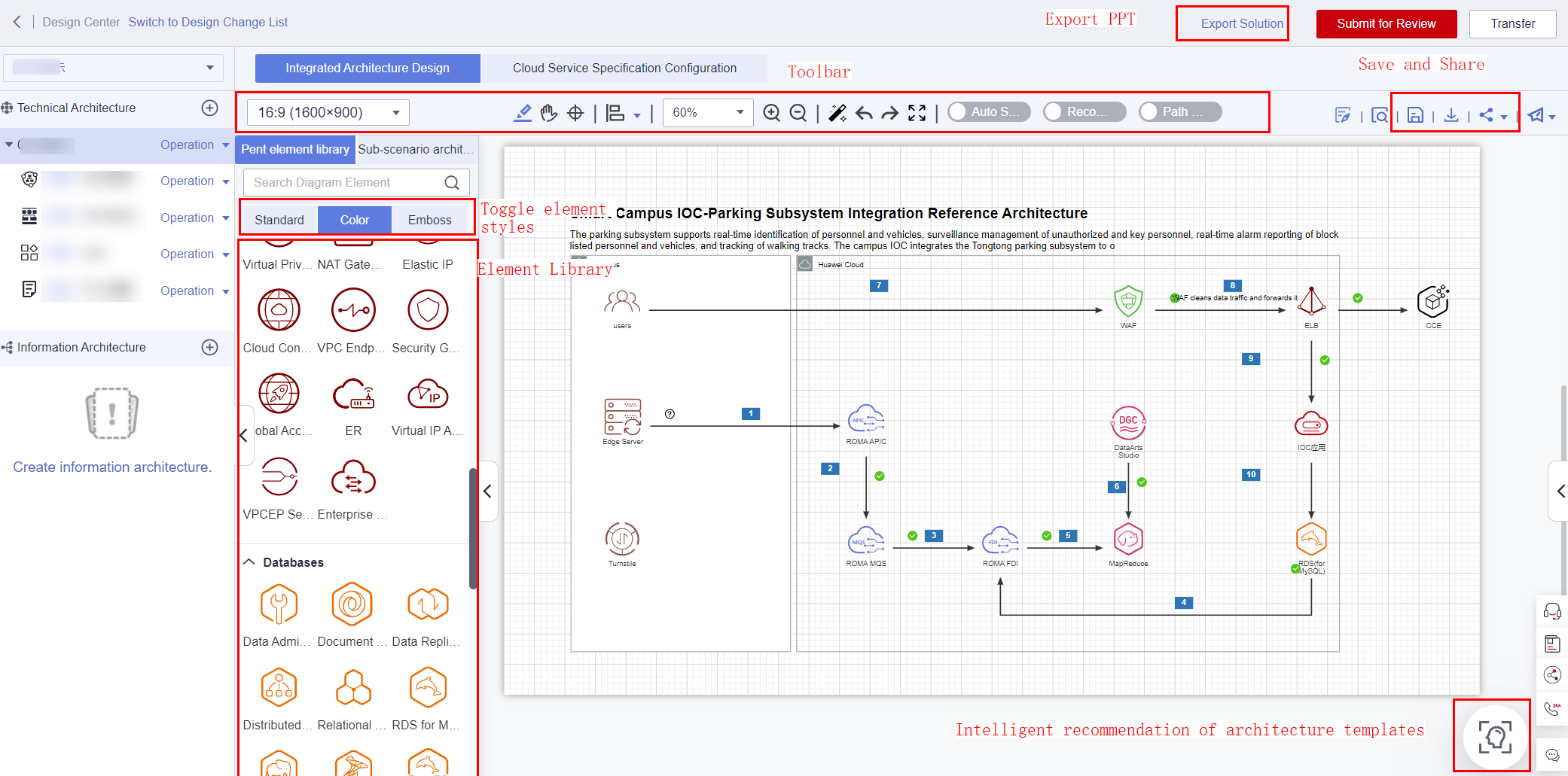
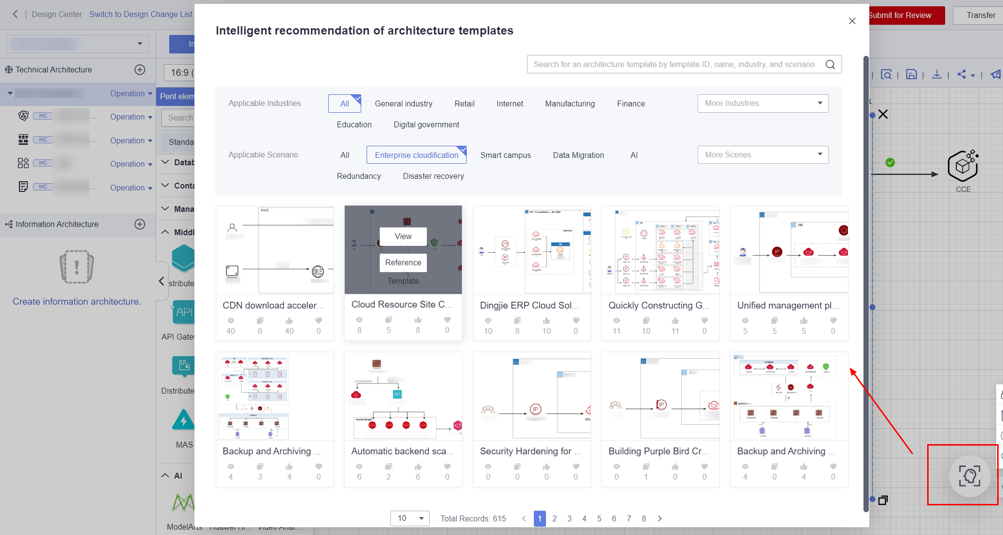
Intelligent Architecture Recommendation
The InnoStage Workbench Design Center can recommend the most suitable solution architecture to you based on the language you entered. You can reference the recommended architecture quickly. In the InnoStage Workbench Design Center, InnoStage Workbench intelligently recommends solutions or architectures based on your solution or architecture information. You can also enter keywords to search for and view the most matched architecture for secondary editing.
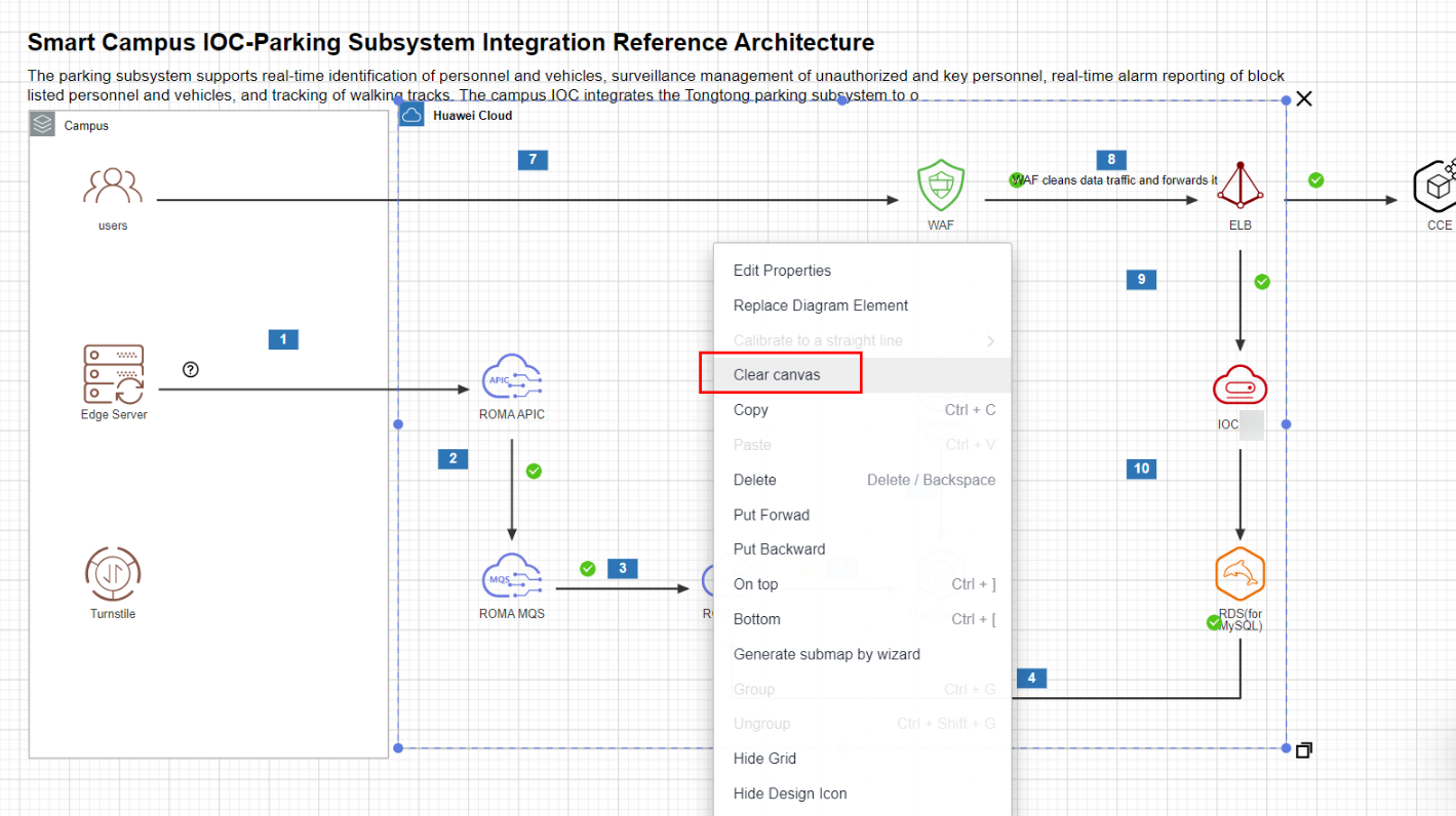
After entering the Design Center, you can use intelligent architecture recommendation to search for the architecture to be referenced. If you want to delete an architecture that is referenced, right-click the architecture and choose [Clear canvas] from the shortcut menu.
Empty Canvas
Right-click the blank area of the canvas and choose [Clear canvas] to clear all contents on the canvas.
Adding Diagram Elements

InnoStage Workbench identifies deployment environment attributes for Huawei Cloud diagram elements. If you cannot find a diagram element, the possible cause is that the diagram element does not match the selected deployment environment. For example, DMS has only the Huawei public cloud attributes. If your current architecture uses Huawei Cloud Stack Online (HCS Online), you cannot find DMS in the diagram element list.
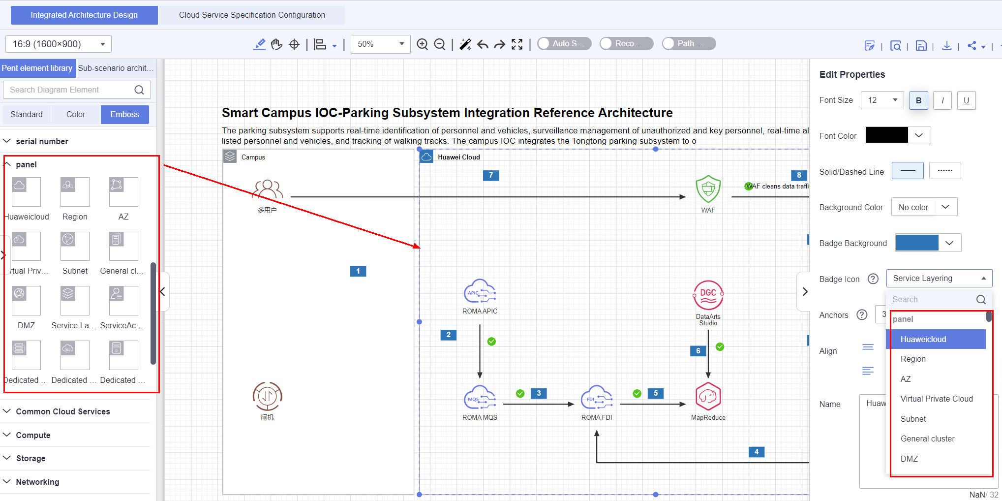
Adding Panel Elements Or Wireframes Elements
Panel diagram elements have been released in the standard and color diagram element modules. There are panel diagram elements for Huawei Cloud, region, AZ, Virtual Private Cloud (VPC), subnet, cluster, DMZ, service layer, account, Dedicated Computing Cluster (DCC), Dedicated Cloud (DeC), and Dedicated Host (DeH). In this example, a turnstile and edge server are deployed in the on-premises data center, and ROMA and DataArts Studio are deployed on Huawei Cloud.
You can also double-click a panel diagram element and modify the badge icon of the panel diagram element on the page that is displayed.
The difference between a panel element and a wireframe element is that a panel element has a hierarchical relationship, while a wireframe element does not have a hierarchical relationship because its interior is hollowed out.
After adding diagram elements, you can adjust them, including selecting diagram elements, moving diagram elements, aligning diagram elements, connecting diagram elements, beautifying diagram elements by one click (adjusting connection lines to straight lines), modifying diagram element attributes such as names and colors, replacing diagram elements, adding service flow description to a diagram element, and copy diagram elements across spaces.
Custom icon and pasting image
The design center supports input images to the canvas. You need to sign the usage statement when using the design center for the first time to use the custom icon and paste screenshots.
- Custom icon: Local images can be uploaded to Custom icon groups for long-term use. Select [Custom icon] to directly operate the default group or click [Create Diagram Element Group] to create a new group. Then, click [Operation] > Select [Upload Diagram Element] or [Upload Element Zip Package] to upload the diagram element or image package. Upload the image to the customized diagram element group and add it to the canvas by dragging.
Figure 9 Design center

- Paste image:The design center can directly paste a screenshot to the canvas. Do not save the screenshot to the local computer or other files. Instead, copy and paste the screenshot.
Adjusting Diagram Elements
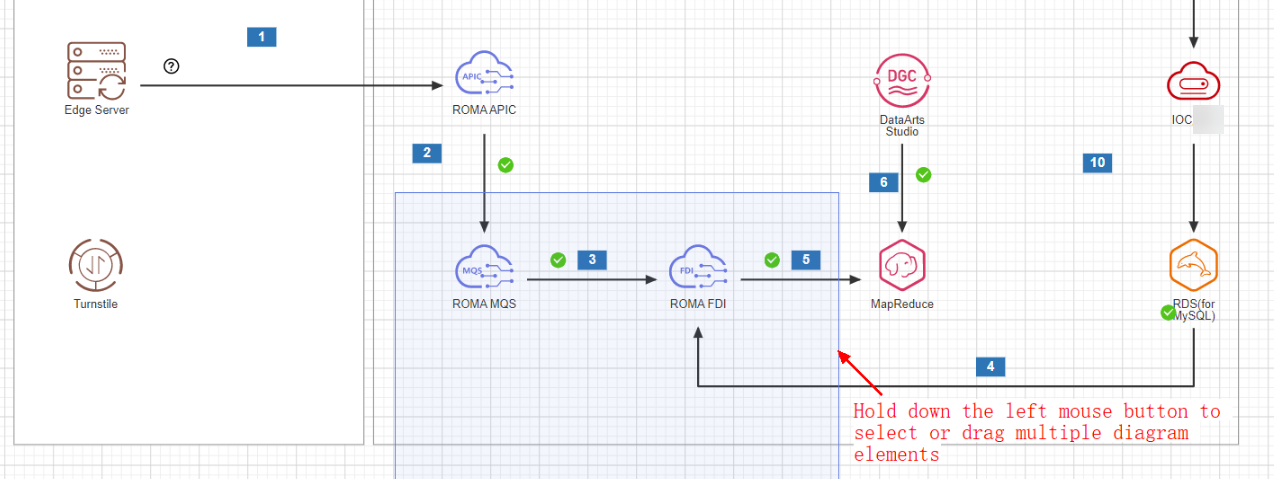
Quickly selecting and moving diagram elements
You can click a diagram element to select it. After selecting a diagram element, you can press Ctrl and click the left mouse button to select other diagram elements. After selecting diagram elements, you can hold down the left mouse button to move the diagram elements. Or you can hold down the left mouse button and drag the mouse to quickly select diagram elements. As shown in the following figure, drag the mouse to select the area where the diagram elements are located. Release the mouse to select the diagram elements in this area. After that, hold down the left mouse button to drag the selected diagram elements.
Aligning diagram elements
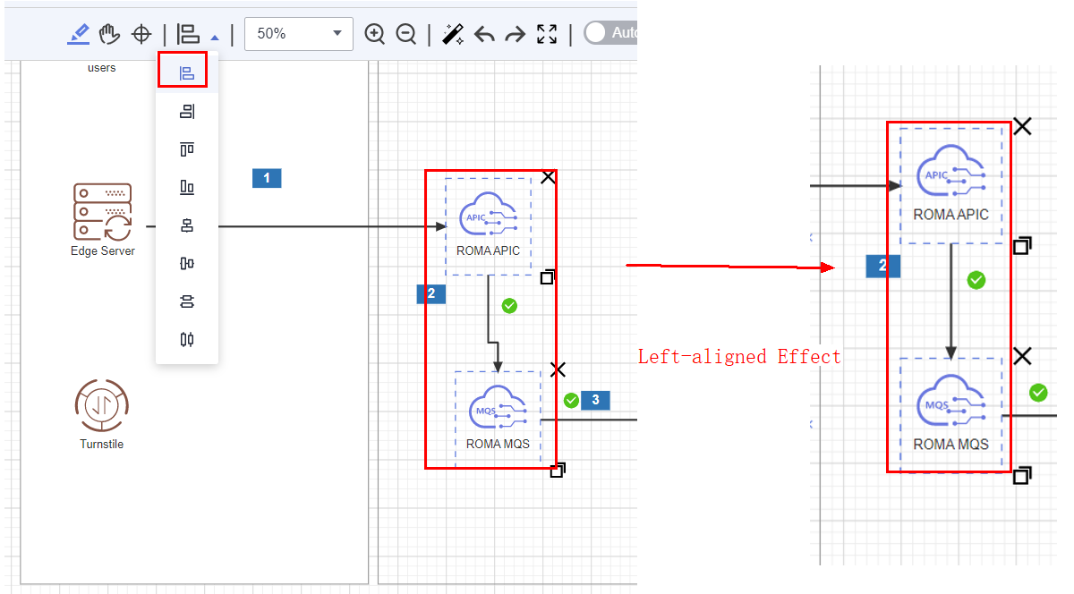
Diagram elements can be aligned left, right, top, bottom, center, and middle. They can also be distributed vertically or horizontally. Press Ctrl and left mouse button to select diagram elements and select an alignment mode. Diagram elements and wireframes can also be aligned.
- Align Left: The selected diagram elements are aligned to the left. This mode is applicable to the scenario where diagram elements are vertically distributed.
- Align Right: The selected diagram elements are aligned to the right. This mode is applicable to the scenario where diagram elements are vertically distributed.
- Align Top: The selected diagram elements are aligned to the top. This mode is applicable to the scenario where diagram elements are horizontally distributed.
- Align Bottom: The selected diagram elements are aligned to the bottom. This mode is applicable to the scenario where diagram elements are horizontally distributed.
- Align Center: The middle lines of selected diagram elements are aligned vertically. This mode is applicable to the scenario where diagram elements are distributed vertically and the sizes of diagram elements are different. For example, the cloud service diagram element is aligned with the wireframe, and the cloud service diagram element is aligned with the panel diagram element.
- Align Middle: The middle lines of selected diagram elements are aligned horizontally. This mode is applicable to the scenario where diagram elements are distributed horizontally and the sizes of diagram elements are different. For example, the cloud service diagram element is aligned with the wireframe, and the cloud service diagram element is aligned with the panel diagram element.
- Distribute Vertically: The selected diagram elements are evenly divided in the vertical direction. The spacing between the diagram elements in the vertical direction is the same.
- Distribute Horizontally: The selected diagram elements are evenly divided in the horizontal direction. The spacing between the diagram elements in the horizontal direction is the same.
Modifying properties of a diagram element
- The name of a common diagram element, for example, the cloud service (ECS) diagram element, and other diagram elements (Wi-Fi), can be changed. You can double-click a diagram element to display the editing page and enter a new diagram element name.
- Double-click a connection line to edit the description of the connection line, for example, the description of the service flow of the connection line.
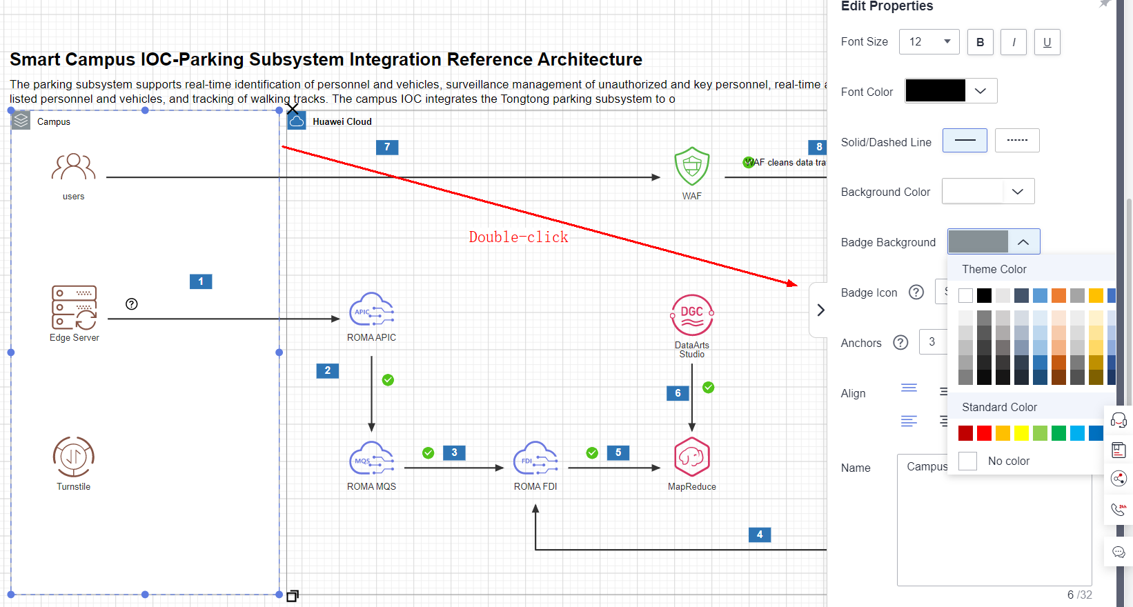
- Base shape diagram elements (such as text boxes, wireframes, and circles) and panel diagram elements support the modification of the font (font size, bold, italic, and underline), font color, line style (solid or dotted line), background color, align (such as align top and align center), badge, and name.
- The font color, background color, and sequence number of the serial number diagram element can be changed. As shown in the following figure, the left part is the device side, and you can modify the information on the diagram element panel. The right part is Huawei Cloud, and you can modify the subnet information.
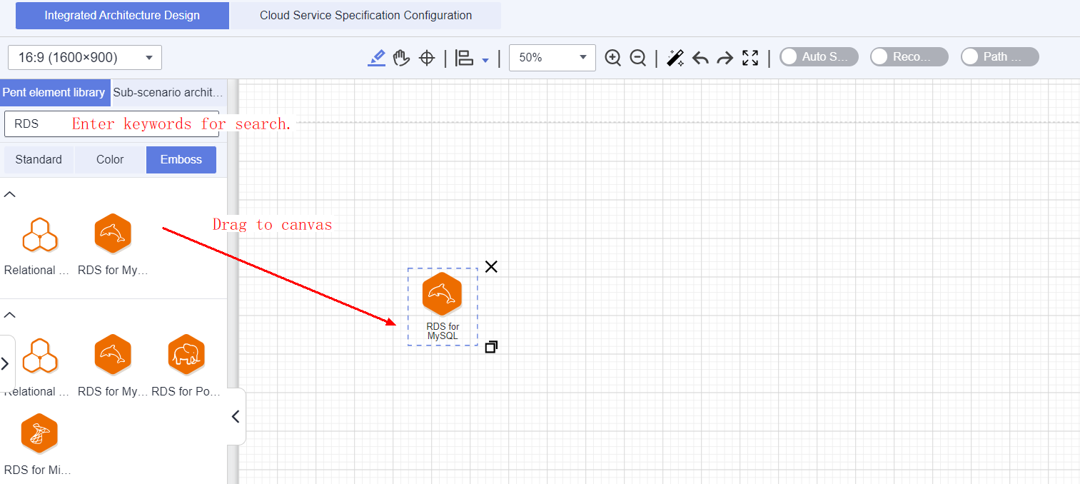
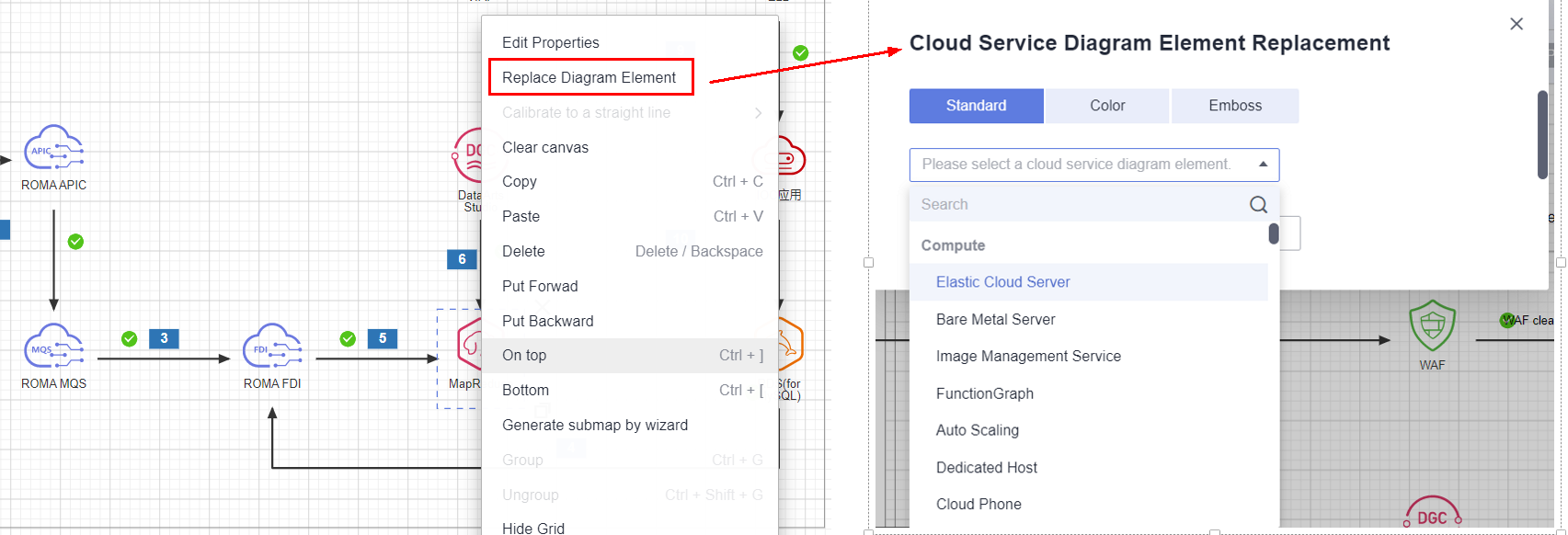
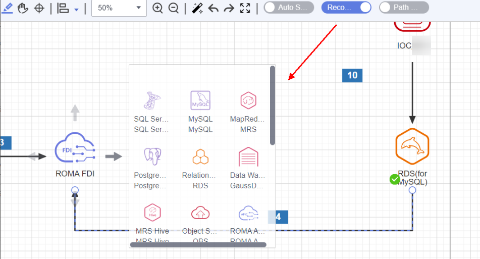
Replacing diagram elements
If a connected diagram element needs to be replaced with another one, for example, the diagram element for RDS needs to be replaced with that for Relational Database Service (RDS) for MySQL, you can use the Replace Diagram Element function. After the replacement, the connection lines related to the diagram element remain unchanged. You can right-click a diagram element, choose [Replace Diagram Element] from the shortcut menu, search for the diagram element, and select the diagram element to be replaced.
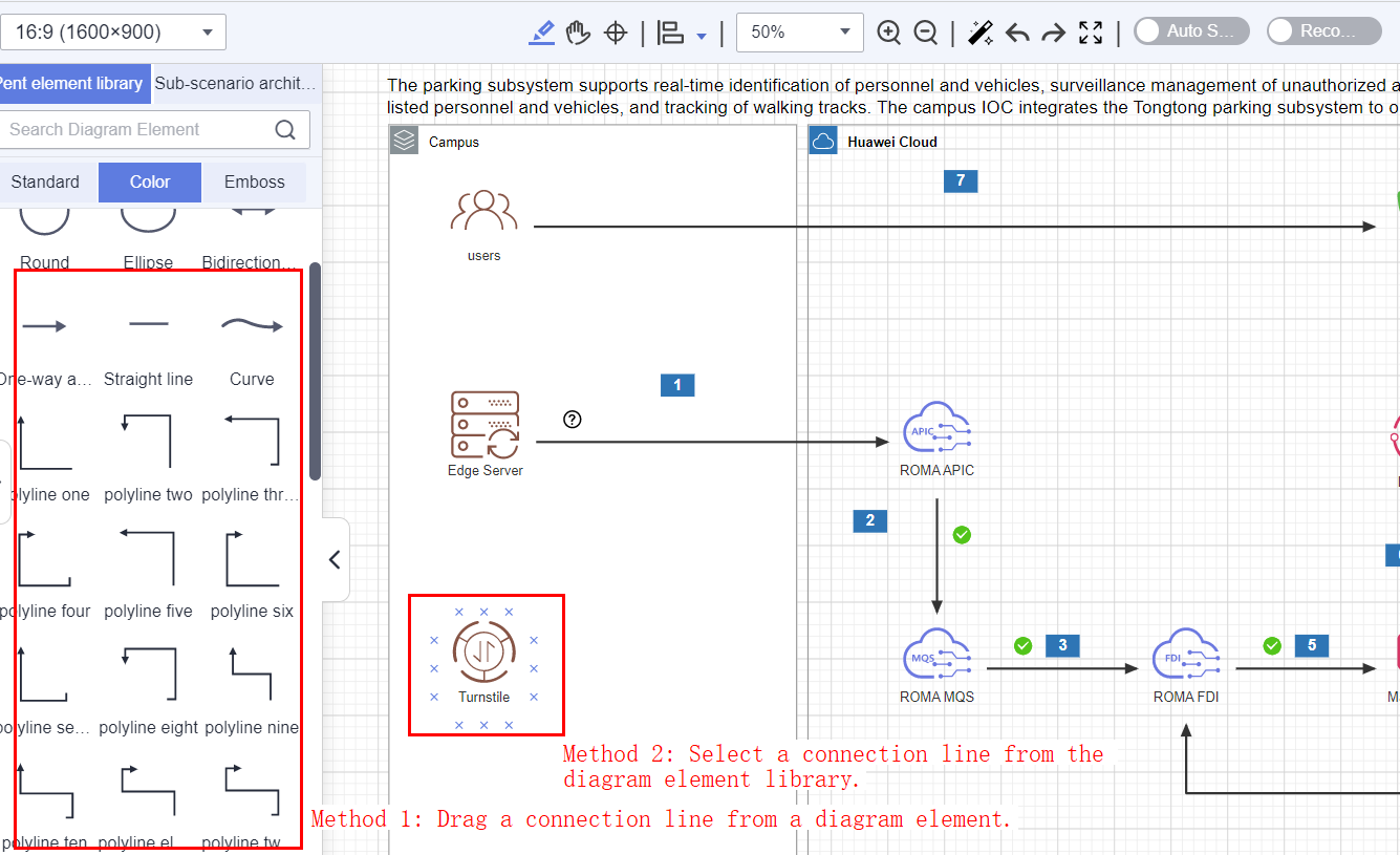
Connecting Diagram Elements
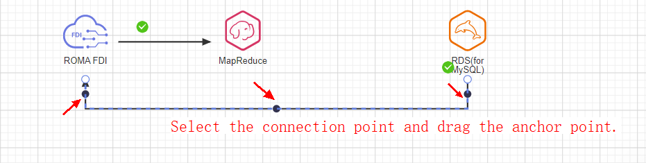
You can use straight lines or polylines to connect diagram elements that will be integrated. You can select straight lines, arrows, curves, or polylines from auxiliary diagram elements. You can also select a diagram element, drag a polyline from it, and connect it to other diagram elements. As shown in the following figure, select a diagram element. The connection nodes around the diagram element are displayed. Move the mouse pointer to the point to be connected, hold down the left mouse button, and drag the connection line to the diagram element to be connected.
If the bending of the connected polyline does not meet the expectation, move the cursor to the polyline and drag it.
Adding Service Flow Descriptions
After adding, modifying, and connecting diagram elements, you can add service flow descriptions for the architecture. The descriptions help clearly identify the relationships between diagram elements and the service flow direction on the architecture.
- You can double-click a connection line to add a description for it. You can move the left mouse button to adjust the position of the description on the connection line. You can also drag a text box from the diagram element library to the corresponding position to add a description.
Copying Diagram Elements Across Spaces
You can copy one or more diagram elements and paste them to the architecture design canvas in the current workspace or other workspaces.
- Select a diagram element. To copy multiple diagram elements, hold down Ctrl and click the diagram elements.
- Press Ctrl+C to copy the diagram elements. You can also right-click and choose Copy from the shortcut menu.
- Open the target canvas and press Ctrl+V. You can also right-click and choose Paste from the shortcut menu.
InnoStage Workbench identifies deployment environment attributes for Huawei Cloud diagram elements. If the deployment environment attributes of a copied diagram element are inconsistent with those of your architecture, the diagram element fails to be saved after being pasted. In this case, delete diagram elements that do not have the deployment environment attributes of your architectures. For example, DMS has only the Huawei public cloud attributes. If you copy the DMS diagram element from the architecture in another space to your current architecture whose deployment environment is HCS Online, the current architecture cannot be saved after the DMS diagram element is pasted. In this case, delete the DMS diagram element.
Adjusting a Canvas
- On the toolbar of the canvas in the Design Center, click the zoom-in or zoom-out buttons to zoom in or zoom out the canvas. You can also press Ctrl and scroll the mouse wheel to zoom in or zoom out the canvas.
- Allows users to undo and restore operations.
- The canvas scale and size can be adjusted.
- You can enter the full-screen mode to focus on design.

Quickly Moving a Canvas
On the canvas page of the Design Center, press the space bar and click the left mouse button to quickly move the canvas.
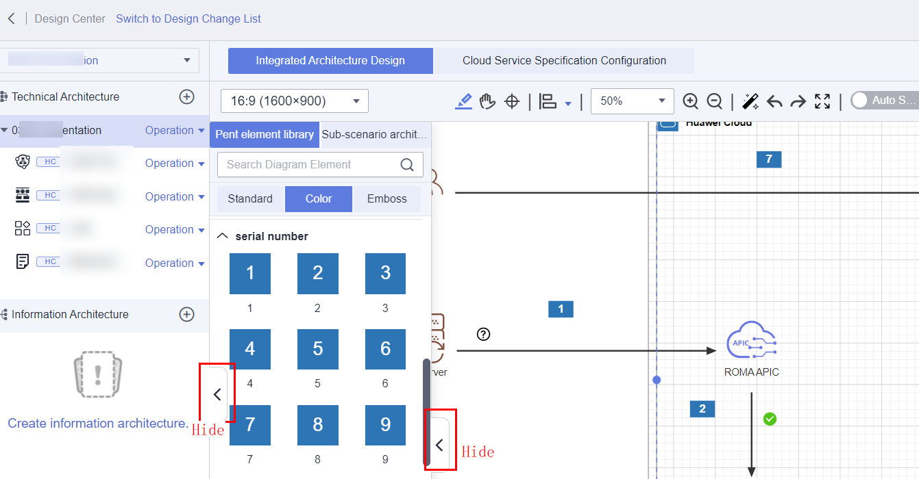
Hiding the Menu or Diagram Element Library
Checking the Design Quality in Real Time
Design rules are preset in the Design Center. The integration path connectivity is checked in real time to ensure the optimal solution design.
- Real-time check of integration paths: Integration paths can be checked in real time based on preset design rules, and check results can be provided.
- Accumulation of design rules: The Huawei Cloud solution team and service product departments will keep accumulating design rules.
- Life cycle management of design rules: The operations team updates the latest design rules and removes expired rules in a timely manner.
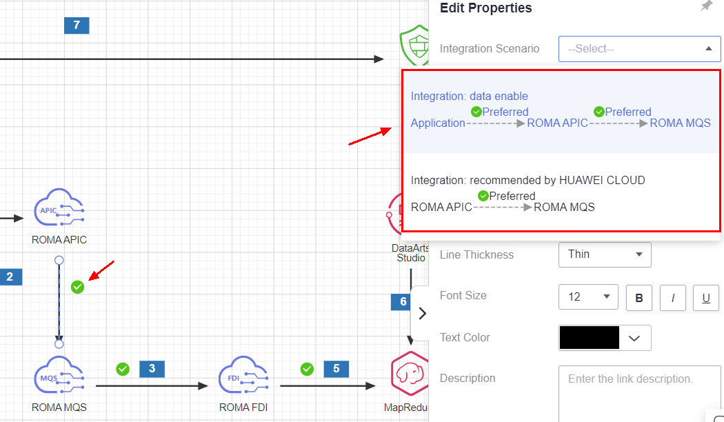
As shown in the following figure, after two diagram elements are connected, if there is a design rule between the two diagram elements, an icon is displayed. You can click the icon to view the detailed prompt information.
Only accounts that have completed real-name authentication can use design rules. For details, see Individual Real-Name Authentication.
Diagram Element Recommendation
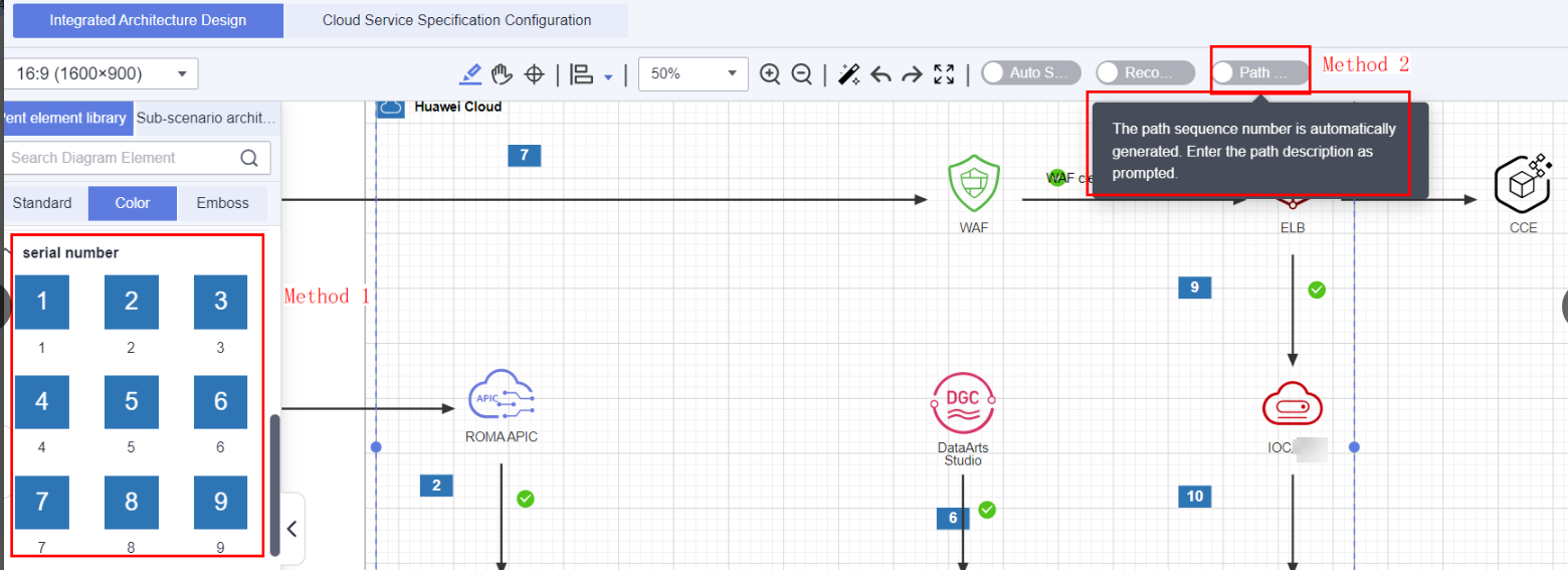
You can enable diagram element recommendation. As shown in the following figure, after Design Rules is enabled, InnoStage Workbench recommends paths for diagram elements with preset design rules.
Identifying Different Deployment Environments
The InnoStage Workbench platform can automatically identify and display cloud service diagram elements that support the deployment environment in the diagram element library based on the selected deployment environment. If you select multiple deployment environments, the diagram element library displays only the cloud services that support these deployment environments.
Auto Save
The integration architecture supports automatic saving. Each time the canvas is modified, the system automatically saves the latest canvas content.
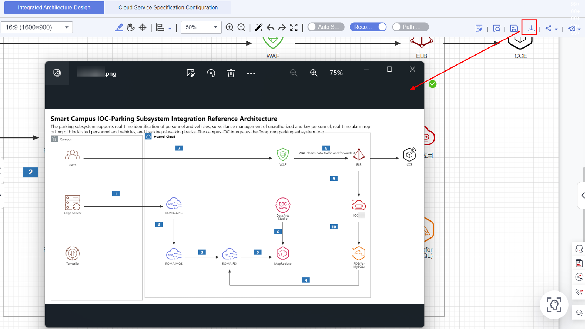
Exporting Architecture Diagrams
Click the Download button on the menu bar on the canvas of the Design Center.
- Select [Export Image] to export the schema as a PNG image.
- Select [Export to PPT] and select the schema to be exported to export the schema as a PPT document.
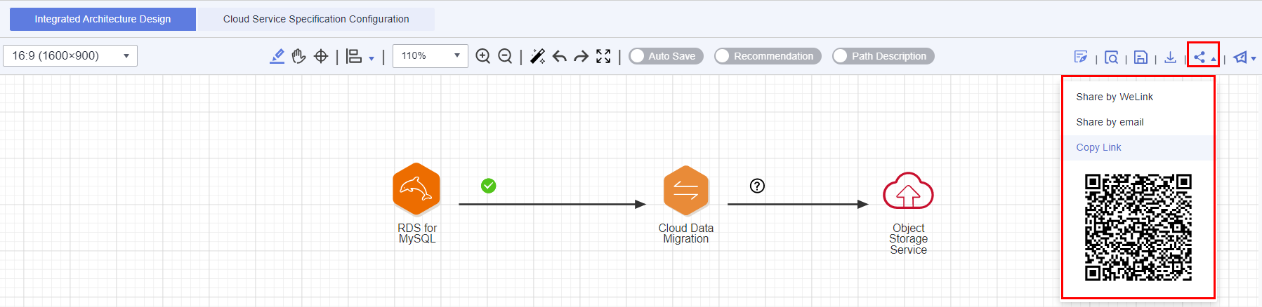
Sharing Architecture
The InnoStage Workbench platform allows you to share architecture design through Link,QR code, and email. You can view the shared architecture without login.
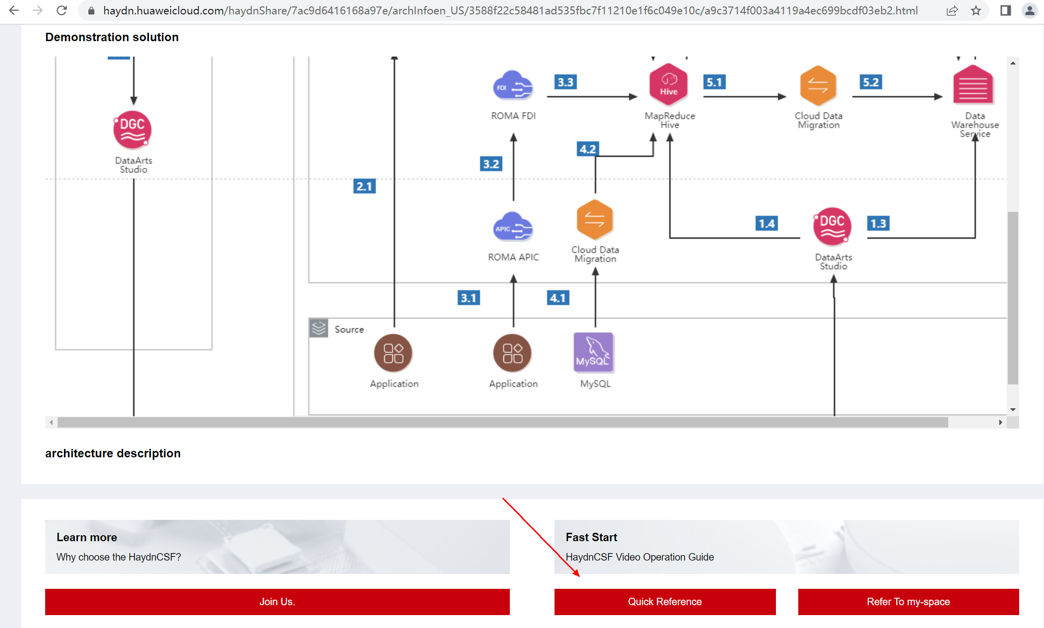
Referencing a Shared Architecture with One Click
You can view the shared architectures without logging in to InnoStage Workbench. To reference the shared technical architecture, you can click [Quick Reference], which allows you to quickly design the architecture without creating a workspace or solution. You can also click [Refer to my-space], select the specified workspace and solution, and change the architecture name to reference to the specified workspace and solution.
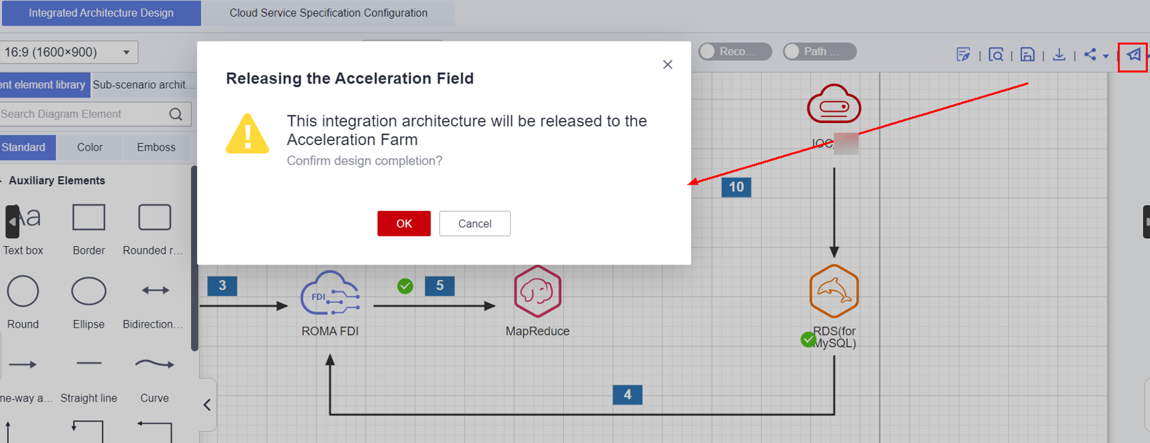
Releasing an technical architecture
You can release the designed architectures to the Solution Acceleration Field so that other InnoStage Workbench users can view or reference your architectures to quickly complete their architecture design. For details about the release process, see Releasing Architecture Template in Accelerator Field.
Feedback
Was this page helpful?
Provide feedbackThank you very much for your feedback. We will continue working to improve the documentation.See the reply and handling status in My Cloud VOC.
For any further questions, feel free to contact us through the chatbot.
Chatbot


