
Using Third-Party Firewalls to Filter Traffic When Connecting an On-premises Data Center to the Cloud
Scenarios
Your on-premises data center communicates with Huawei Cloud through Direct Connect or VPN. A third-party virtual firewall is deployed on the cloud to filter traffic.
This section describes how to use a third-party virtual firewall when connecting your on-premises data center to multiple VPCs.
Solution Advantages
- You can use third-party firewalls.
- The traffic between the cloud and the on-premises data center will pass through the third-party virtual firewall.
- You can define security rules as required.
Typical Topology
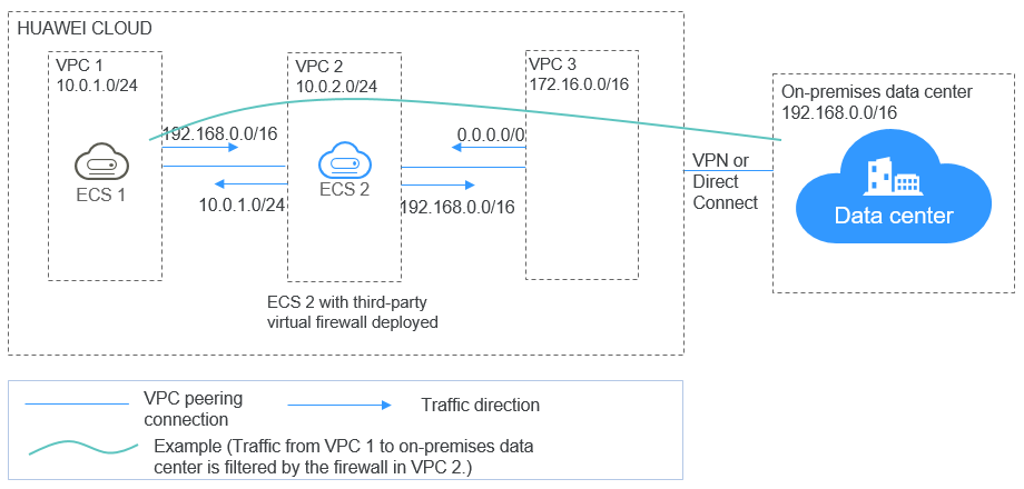
Assume that your services are deployed in VPC 1, VPC 2, VPC 3, and your on-premises data center, and you need to use a third-party virtual firewall on the cloud. You can configure the virtual firewall on ECS 2 in VPC 2 and use VPC peering connections and configure routes to enable communication between the VPCs. In addition, you need to create a Direct Connect connection to enable communication between VPC 3 and the on-premises data center.
The deployment diagram is as follows:
Prerequisites
The subnet CIDR blocks of VPC 1, VPC 2, and VPC 3 cannot overlap with each other. Otherwise, communication through VPC peering connections will fail.
Procedure
- Create VPCs.
Create VPC 1, VPC 2, and VPC 3.
For details, see Creating a VPC with a Subnet.

The CIDR blocks of VPC 1, VPC 2, and VPC 3 cannot overlap with each other. For example, the CIDR block of VPC 1 is 10.0.1.0/24, VPC 2 is 10.0.2.0/24, and VPC 3 is 172.16.0.0/16.
- Create ECSs.
- Create ECS 1 and ECS 2, which belong to the VPC 1 subnet and VPC 2 subnet, respectively.
For details, see Purchasing an ECS in Custom Config Mode.
The source/destination check must be disabled for the ECS 2 network interface.
- Deploy a third-party virtual firewall on ECS 2.
- Enable IP forwarding on ECS 2.
- Run the following command to switch to user root:
su root
- Run the following command to check whether IP forwarding is enabled:
cat /proc/sys/net/ipv4/ip_forward
In the command output, 1 indicates that IP forwarding is enabled, and 0 indicates that IP forwarding is disabled.
- If 1 is displayed, no further action is required.
- If 0 is displayed, go to the next step.
- Run the following command to enable IP forwarding:
- Run the following command to open the /etc/sysctl.conf file:
vim /etc/sysctl.conf
- Press i to enter the editing mode.
- Modify or add the following content:
net.ipv4.ip_forward = 1 #Enable IPv4 forwarding.
net.ipv6.conf.all.forwarding = 1 #Enable IPv6 forwarding if IPv6 needs to be supported.
- Press ESC to exit and enter :wq! to save the configuration.
- Run the following command to open the /etc/sysctl.conf file:
- Run the following command to make the modification take effect:
The preceding configuration takes effect permanently and does not become invalid after the ECS is restarted.
- Run the following command to switch to user root:
- Create ECS 1 and ECS 2, which belong to the VPC 1 subnet and VPC 2 subnet, respectively.
- Create VPC peering connections.
Create VPC peering connections between VPC 1 and VPC 2, VPC 2 and VPC 3 to enable communications between them.
- If your VPCs are in the same account, see the step "Create a VPC Peering Connection" in Creating a VPC Peering Connection to Connect Two VPCs in the Same Account.
- If your VPCs are in different accounts, see the steps "Create a VPC Peering Connection" and "Peer Account Accepts the VPC Peering Connection Request" in Creating a VPC Peering Connection to Connect Two VPCs in Different Accounts.
- Create a route table for a subnet.
Create a custom route table and associate it with the VPC 2 subnet to control the outbound traffic.
For details, see Creating a Custom Route Table.
- (Optional) Assign a virtual IP address and bind it to ECSs. You can create two ECSs in VPC 2 and bind them to the same virtual IP address so that they can work in the active and standby mode. If the active ECS is faulty and cannot provide services, the virtual IP address will be dynamically switched to the standby ECS to continue providing services. Skip this step if the standby ECS is not required.
- Assign a virtual IP address in the VPC 2 subnet.
For details, see Assigning a Virtual IP Address.
- Bind the virtual IP address to ECS 2.
For details, see Binding a Virtual IP Address to an Instance or EIP.
- Assign a virtual IP address in the VPC 2 subnet.
- Create a Direct Connect connection.
Use a Direct Connect connection to enable communication between VPC 3 and the on-premises data center. For details, see Using Direct Connect to Connect an On-Premises Data Center to the Cloud.
- Configure routes. You can configure routes to forward traffic to a next hop and finally to a destination.
- Add the following route to the default route table of VPC 1:
Add a route to forward traffic from VPC 1 to the on-premises data center, set the destination of the route to the CIDR block of the on-premises data center, and the next hop of the route to the VPC peering connection between VPC 1 and VPC 2.
- Add the following route to the default route table of VPC 2:
Set the destination of the route to 0.0.0.0/0, and the next hop of the route to ECS 2.
If there are two ECSs that use the same virtual IP address to work in the active and standby mode, the next hop should be the virtual IP address.
- Add the following routes to the route table of VPC 2 subnet:
- Add a route to forward traffic from VPC 2 to VPC 1, set the destination of the route to the CIDR block of VPC 1, and the next hop of the route to the VPC peering connection between VPC 1 and VPC 2.
- Add a route to forward traffic from VPC 2 to the on-premises data center, set the destination of the route to the CIDR block of the on-premises data center, and the next hop of the route to the VPC peering connection between VPC 2 and VPC 3.
- Add the following route to the default route table of VPC 3:
Set the destination of the route to 0.0.0.0/0, and the next hop of the route to the VPC peering connection between VPC 2 and VPC 3.
A Direct Connect connection has been created in 6. Thus, a route to the Direct Connect connection will be automatically delivered by the system.
- Add the following route to the default route table of VPC 1:
Verification
Log in to ECS 1 and then access your on-premises data center from ECS 1. Check whether ECS 2 can receive packets sent from ECS 1 to the data center. Check whether the packets pass through and are filtered by the firewall on ECS 2.
Feedback
Was this page helpful?
Provide feedbackThank you very much for your feedback. We will continue working to improve the documentation.See the reply and handling status in My Cloud VOC.
For any further questions, feel free to contact us through the chatbot.
Chatbot


