Tutorial: Converting a Physical Cluster That Contains Data into a Logical Cluster
Scenario
A large database cluster usually contains a large amount of data put in different tables. With the resource management feature, you can create resource pools to isolate the resources of different services. Different service users can be allocated to different resource pools to reduce resource (CPU, memory, I/O, and storage) competition between services.
As the service scale grows, the number of services in the cluster system also increases. Creating multiple resource pools becomes less effective in controlling resource competition. DWS uses the distributed architecture and its data is distributed on multiple nodes. Each table is distributed across all DNs in the cluster, an operation on a data table may involve all DNs, which increases network loads and system resource consumption. To solve this problem, scale-out is not effective. You are advised to divide a DWS cluster into multiple logical clusters.
You can create a separate logical cluster and assign new services to it. This way, new services have little impact on existing services. Also, if the service scale in existing logical clusters grows, you can scale out the existing logical clusters.
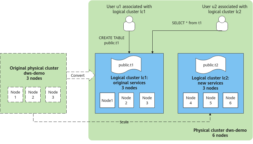
Figure 1 shows an example. The original service data tables of a company are stored in the original physical cluster dws-demo (in green). After services are switched over to the logical cluster lc1 (in blue), a new logical cluster lc2 is added to the physical cluster through scale-out. The original service data tables are switched to logical cluster lc1, and new service data tables are written to logical cluster lc2. In this way, the data of old and new services is isolated. User u2 associated with logical cluster lc2 can access the tables of logical cluster lc1 across logical clusters after authorization.
- Cluster scale: Scale out the original physical cluster from three nodes to six nodes and split it into two logical clusters.
- Service isolation: New and old service data is isolated in different logical clusters.
Creating a Cluster and Preparing Table Data
- Create a cluster. For details, see Creating a Dedicated GaussDB(DWS) Cluster.
- After connecting to the database, create table name as the system administrator dbadmin and insert two data records into the table.
1
2
CREATE TABLE name (id int, name varchar(20));
INSERT INTO name VALUES (1,'joy'),(2,'lily');
Converting to Logical Cluster lc1

During the conversion, you can run simple DML statements, such as adding, deleting, modifying, and querying data. Complex DDL statements, such as operations on database objects, will block services. You are advised to perform the conversion during off-peak hours.
- Log in to the DWS console.
- In the navigation pane on the left, choose Dedicated Clusters > Clusters. Click the name of a cluster to go to the Cluster Information page.
- Toggle on the Logical Cluster switch.
- In the navigation pane on the left, choose Logical Clusters.
- Click Add Logical Cluster in the upper right corner, enter the logical cluster name lc1, and click OK.
During the switchover, the current cluster is unavailable. Wait for about 2 minutes (the conversion time varies depending on the service data volume). If lc1 is displayed on the logical cluster page, the conversion is successful.
Figure 2 Adding a logical cluster
Adding Nodes to the elastic_group Cluster
- Return to the Cluster Management page. In the Operation column of the cluster, choose More > Scale Node > Scale Out.
Before scaling out the cluster, it is crucial to verify if it meets the inspection conditions. Click Immediate Inspection to complete the inspection and proceed to the next step only if it passes. For more information, see Viewing Inspection Results.
- Set New Nodes to 3. Enable Online Scale-out. Set elastic_group as the target logical cluster. Confirm the settings, select the confirmation check box, and click Next: Confirm.
- Click Next: Confirm, and then click OK.
Wait for about 10 minutes until the scale-out is successful.
Adding Logical Cluster lc2
- On the Cluster Management page, click the name of a cluster to go to the cluster details page. In the navigation pane, choose Logical Clusters.
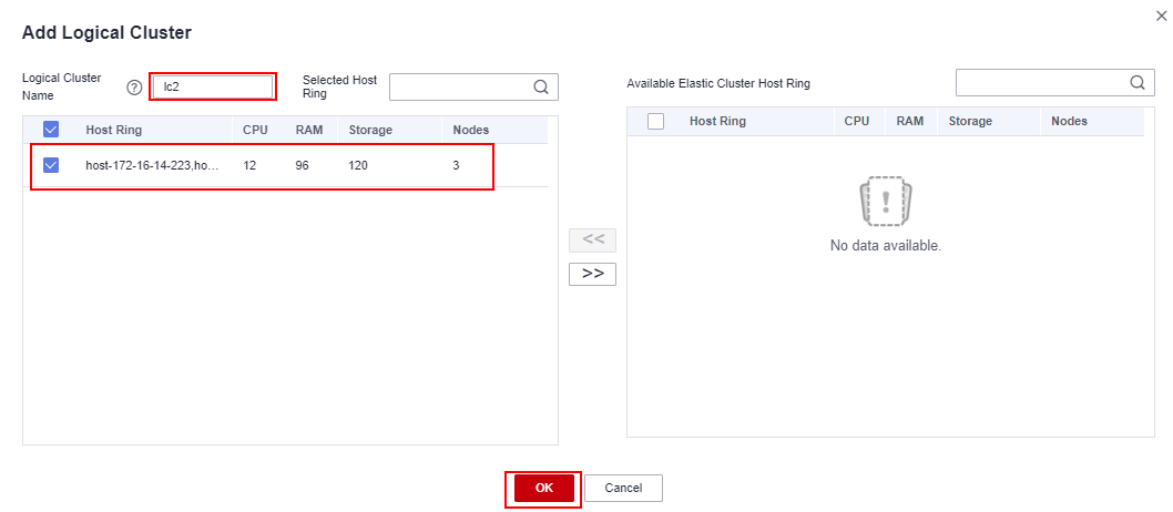
- Click Add Logical Cluster in the upper right corner, select three nodes from the right pane to add to the left pane, enter the logical cluster name lc2, and click OK.
After about 2 minutes, the logical cluster is successfully added.
Figure 3 Adding a logical cluster Figure 4 Selecting a host ring
Creating Logical Clusters, Associating Them with Users, and Querying Data Across Logical Clusters
- Connect to the database as the system administrator and run the following SQL statement to query the original service table name.
Verify that service data can be queried after the conversion.
1SELECT * FROM name;
- Create logical clusters lc1 and lc2 for u1 and u2, respectively.
1
2
CREATE USER u1 NODE GROUP "lc1" PASSWORD '{password}';
CREATE USER u2 NODE GROUP "lc2" PASSWORD '{password}';
- Log in to the database as user u1, create table u1.t1, insert two data records into the table, and grant user u2 the permission to access the table.
1
2
3
4
CREATE TABLE u1.t1 (id int, name varchar(20));
INSERT INTO u1.t1 VALUES (1,'joy'),(2,'lily');
GRANT USAGE ON SCHEMA u1 TO u2;
GRANT SELECT ON TABLE u1.t1 TO u2;
- Log in to the database as user u2 and query data in the original service table t1. A message is displayed, indicating that you do not have the permission to access logical cluster lc1. The result shows that even if user u1 has authorized user u2 to access the table, the table cannot be accessed because it is in different logical clusters. This proves that data is isolated between logical clusters.
1SELECT * FROM u1.t1;

- Switch back to system administrator dbadmin and grant the access permission of logical cluster lc1 to user u2.
1GRANT USAGE ON NODE GROUP lc1 TO u2;
- Switch to user u2 and query the t1 table. This proves that the user bound to logical cluster lc2 can query the original service table t1 across logical clusters. In this way, data is shared between logical clusters.
1SELECT * FROM u1.t1;

Feedback
Was this page helpful?
Provide feedbackThank you very much for your feedback. We will continue working to improve the documentation.


