
Drawing and Governing Deployment Architectures
Scenarios
You can draw an application architecture using basic canvas elements such as border, element node, and edge. After saving the architecture, you can view the architecture details on the Architecture Governance page. On that page, you can view all architectures and SLO values. You can also modify the deduction item configurations of an application, and re-evaluate SLO values of the architecture.
Drawing a Deployment Architecture
- Log in to COC.
- In the navigation pane, choose Resilience Center > Architecture Design.
- Click the name of the target deployment architecture in the Architecture Name/Description column. The Architecture Governance page is displayed.
- Click Architecture Drawings.
- Draw an architecture.
- Select a diagram element in the left list and drag it to the canvas.
Table 1 Diagram elements Element Type
Description
Example Value
Border
A border is used to wrap canvas elements that need to be connected in parallel. You can double-click a border to configure the parallel relationship.
Basic Diagram Elements > Border
Element node
An element node represents a specific cloud service. Each element node has an SLO value.
Compute > Elastic Cloud Server
Edge
An edge represents a serial relationship between canvas elements. Only one edge can be dragged out to connect to another element on a canvas, and can be connected by only one edge.
-
- Drag an edge from one element to connect to another element in the canvas to establish a serial relationship between elements.
- Drag a border from the diagram element list on the left to the canvas and use another element to establish a parallel relationship in it. This element can be a nested border or an element node.
- Double-click the border to be connected in parallel and configure parameters on the displayed page.
Table 2 Basic parameters Parameter
Description
Enable parallel configuration
Whether to enable parallel configuration. If this parameter is enabled, the current border is enabled for parallel configuration.
Redundancy mode
Voting decision-making: In a K-out-of-N system, when N parallel nodes work at the same time, they share workloads evenly to ensure that at least K nodes are running normally. That is, the system can tolerate a maximum of N – K node failures. By default, K is set to 1, ensuring that at least one parallel node is running normally. In this case, the nodes are fully parallel, and the SLO availability calculation yields a probability of ≥ 1. For other values of K, the SLO availability calculation results in a probability of ≥ K.
- Number of votes (K): The redundancy mode of voting decision-making ensures that at least K parallel nodes are normal. The default value is 1.
- Number of active nodes: N parallel nodes that work at the same time in the redundancy mode of voting decision-making.
N + M active/standby: N active nodes and M standby nodes. Only when one of the active nodes is faulty, the standby nodes start to work.
- Number of active nodes: N active nodes in N + M active/standby redundancy mode.
- Number of standby nodes: M standby nodes in N + M active/standby redundancy mode.
N + 1 redundancy: N + 1 parallel nodes work at the same time and share even workloads. That is, at least N parallel nodes are normal, and the system can work properly only when there is no more than one faulty parallel node.
Number of active nodes: N parallel nodes working at the same time in N + 1 redundancy mode.
Active/standby mode in the border
The border can function as the active or standby node in the N + M active/standby redundancy mode. The options are as follows:
- Active
- Standby
Active/Standby mode of a diagram element node
The diagram element node functions as the active or standby node in the N + M active/standby redundancy mode. The options are as follows:
- Active
- Standby
- Select a diagram element in the left list and drag it to the canvas.
- Click Save.
The architecture drawing is complete.
Governing a Deployment Architecture
- Log in to COC.
- In the navigation pane, choose Resilience Center > Architecture Design.
- Click the name of the target deployment architecture in the Architecture Name/Description column. The Architecture Governance page is displayed.
- Click Deduction Item Configuration and configure the parameters on the displayed page. If you set a larger number for parameters, the SLO value you calculated for the architecture will be a smaller one.
Figure 1 Configuring deduction items

Table 3 Parameters for deduction item configuration Parameter
Description
Number of Planned Changes
Number of plan changes within one year.
Average change recovery duration (Minute)
Average recovery duration of each change within one year, in minutes.
Number of overload events
Number of overload incidents that may occur within one year.
Average recovery duration of overload incidents (Minute)
Average recovery duration of each overload incident within one year, in minutes.
Whether flow control measures are taken
Flow control switch. If you set this parameter to Yes, the Number of overload events and Average recovery duration of overload events (Minute) parameters are invalid and their values are the default value 0.
Number of other fault events
Number of other fault incidents that may occur within one year.
Mean Recovery Duration of Other Faults (Minute)
Average recovery duration of other fault incidents within one year, in minutes.
- Click OK.
- Click Immediate assessment to re-evaluate the SLO value of the architecture.
The architecture is governed.
Figure 2 Evaluating an architecture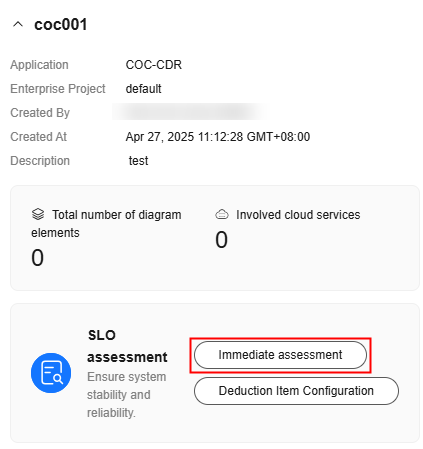
Feedback
Was this page helpful?
Provide feedbackThank you very much for your feedback. We will continue working to improve the documentation.See the reply and handling status in My Cloud VOC.
For any further questions, feel free to contact us through the chatbot.
Chatbot


