Developing a Smart Street Light Using NB-IoT BearPi
Scenarios
Smart street lights play an important role in the intelligent transformation of city roads. They save energy in public lighting, reduce traffic accidents caused by poor lighting, and contribute to many other aspects in our community. As a common public facility, street lights can well exemplify how intelligence is transforming the world and implemented in our daily lives.
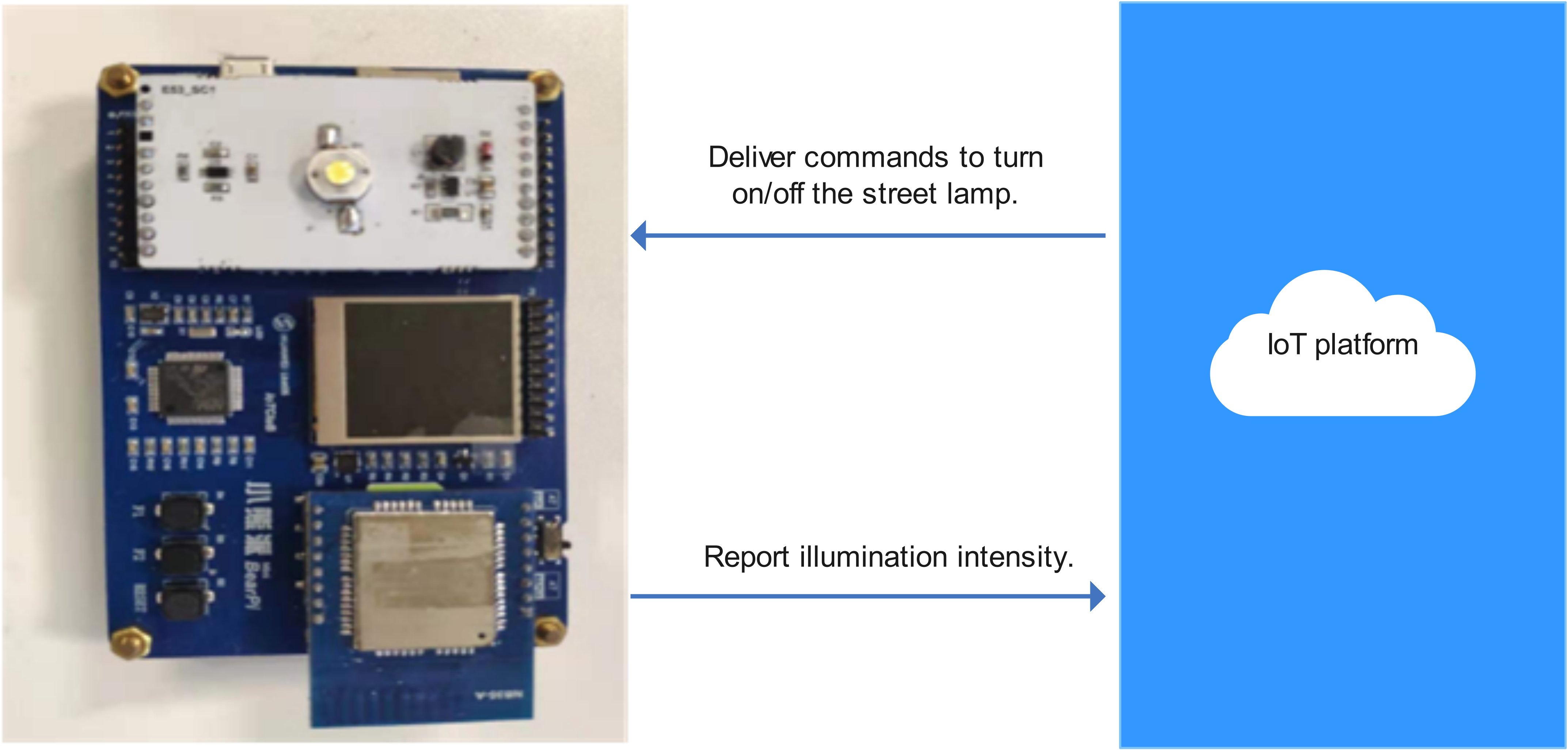
This section describes how to build a smart street light solution in just 10 minutes based on Huawei one-stop development tool platform (the IoT Link plug-in on Visual Studio Code), covering the device (BearPi development kit) and Huawei Cloud IoTDA. A smart street light detects and reports the illumination intensity to the IoTDA console. The LED light switch can be remotely controlled on the IoTDA console.
Development Environment
- Hardware: BearPi-IoT development suite (including NB-IoT cards, NB-IoT modules, smart street light function modules, and USB data cables)
- Software: Visual Studio Code, the IoT Link plug-in, Huawei Cloud IoTDA service, and 64-bit Windows 7 or later (64-bit Windows 10 is used in the following demonstration.)
Development Process
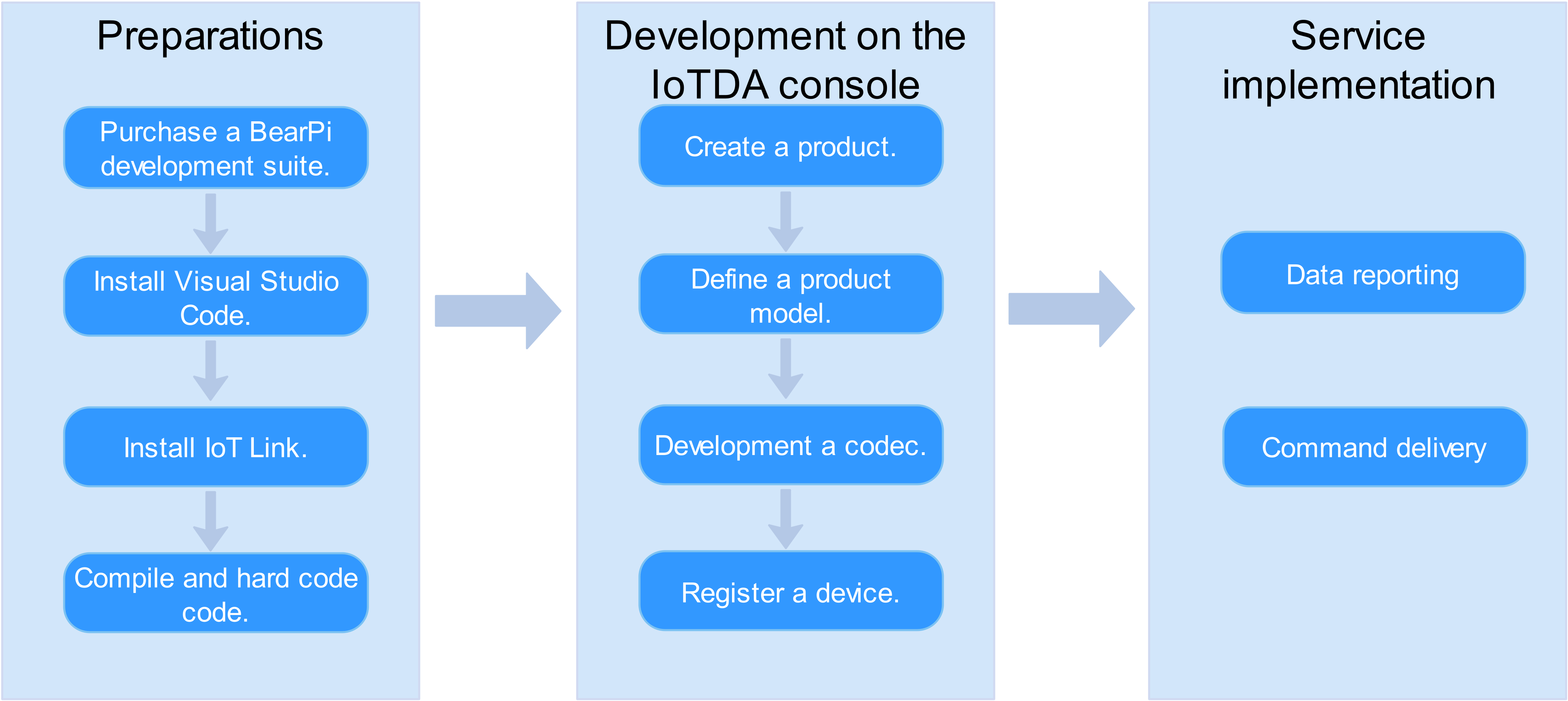
The following figure shows the end-to-end process of developing a smart street light.
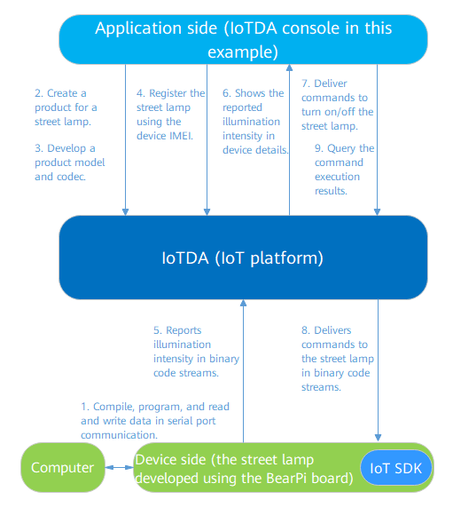
In this scenario, a device interacts with the platform using LwM2M (NB-IoT card). The application displays property changes of the device and delivers commands to the device.
Introduction to the BearPi Development Board
The development board is a sensing device in the IoT architecture. This type of device usually includes a sensor, communications module, chip, and operating system. To improve scalability of the development board, the BearPi development board does not use a conventional onboard design. Instead, it uses replaceable sensor and communications module expansion boards. The communications module is an entrance and exit of data transmission. Common communications modules include NB-IoT, Wi-Fi, and 4G ones. A chip controls a device. The development board has a built-in low-power STM32L431 chip as the main control chip (MCU). The operating system is Huawei LiteOS, which provides various device-cloud interworking components.
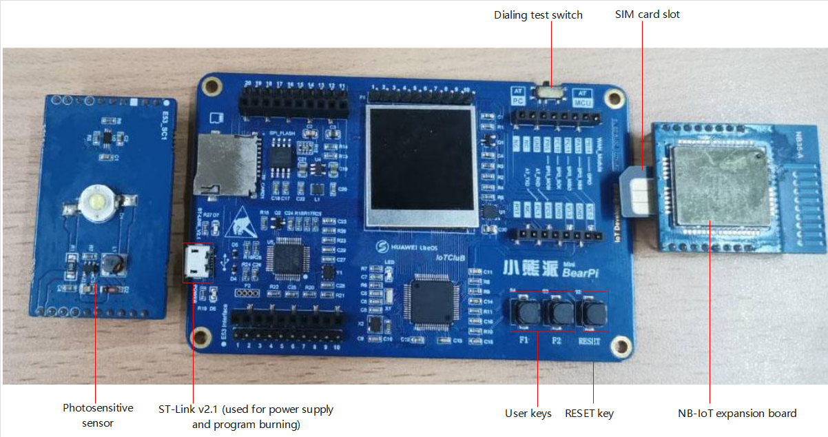
To facilitate development and debugging, the development board uses the onboard ST-Link of the 2.1 version, as shown in Figure 1. It provides functions such as online debugging and programming, drag-and-drop download, and virtual serial port. An LCD screen with a resolution of 240 x 240 is installed at the center of the board to display sensor data and other debug logs. Below the LCD screen is the MCU.
There is a DIP switch in the upper right corner of the development board. When you set the switch to the AT-PC mode, use the serial port assistant on the computer to send AT commands to debug the communication module. When you set it to the AT-MCU mode, use the MCU to send AT commands to interact with the communication module and sends the collected sensor data to the cloud through the communication module.
Connecting Hardware
- Insert the NB-IoT card into the SIM card slot of the NB-IoT expansion board. Ensure that the notch-end faces outwards, as shown in Figure 2.
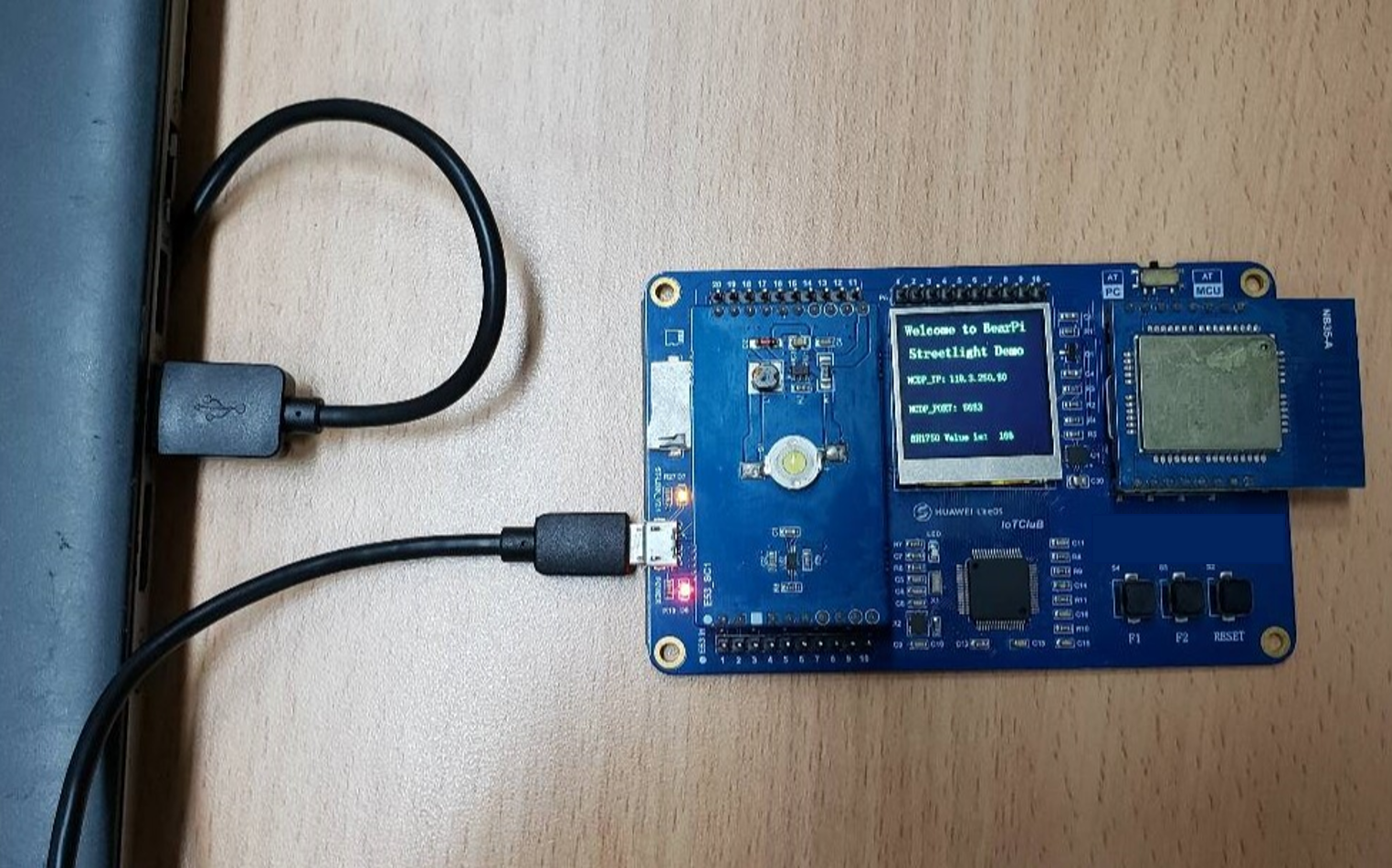
- Insert the photosensitive sensor and NB-IoT expansion board into the development board. Ensure they are inserted in the correct direction. Use a USB data cable to connect the development board to the computer. If the screen displays information and the power indicator is on, the development board is powered on.
Installing the IoT Link Studio Plug-in
IoT Link Studio is an integrated development environment (IDE) developed for IoT devices. It provides one-stop development capabilities, such as compilation, programming, and debugging, and supports multiple programming languages, such as C, C++, and assembly language.
- Obtain the operating system information. For example, on Windows 10, enter pc in the Run window, and click Properties to view the system information.
Figure 3 Obtaining the system configuration
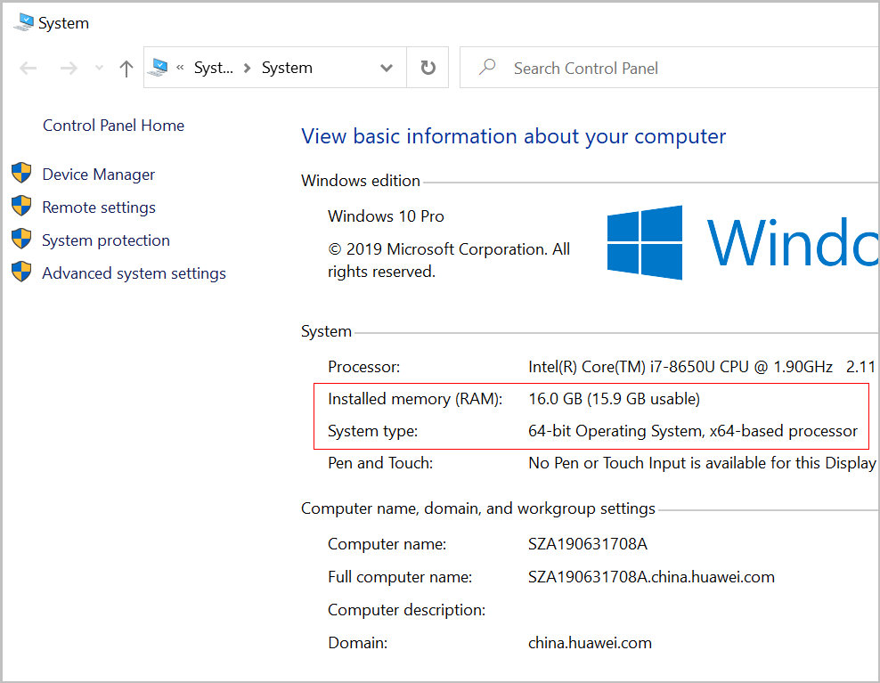
- Click here to download and install a Visual Studio Code version that suits your computer system. This section uses 64-bit Windows 10 as an example. Download version 1.49. Other versions do not support IoT Link.
Figure 4 Downloading Visual Studio Code

Note: Visual Studio Code does not support macOS.
- After Visual Studio Code is installed, in its plug-in store, search for IoT Link and install it.
- Perform the initial startup configuration.
When the IoT Link Studio is started for the first time, it automatically downloads the latest SDK package and GCC dependency environment. Ensure that the network is available. Do not close the window during the installation. After the installation is complete, restart the Visual Studio Code for the plug-in to take effect.

If a proxy is required, click
 in the lower left corner of the Visual Studio Code home page and choose , and set Use the proxy support for extensions to on.
 - If the automatic downloading failed, manually download SDK package, change the file name to IoT_LINK, and save it to the C:\Users\${User name}\.iotlink\sdk directory. Open the Visual Studio Code again. The following figure shows the directory format.
Configuring an IoT Link Studio Project
- Click Home on the toolbar at the bottom of Visual Studio Code.
- Home is used to manage the IoT Link project.
- Serial is used to enter AT commands to check the status of the development board.
- Build is used to compile the sample code (displayed after Step 3).
- Download is used to hard code to the MCU (displayed after Step 3).
- Configure the cross compilation toolchain. On the displayed page, click IoT Link Settings and select a toolchain. If the GCC tool directory or file does not exist, download and install it.

The version of the compilation toolchain downloaded by BearPi STM32431 is win32.zip.
- On the displayed page, click Create IoT Project, enter the project name and project directory, and select the hardware platform and sample project template of the developer board.
- Project Name: Enter a project name, for example, QuickStart.
- Project Path: You can use the default installation path or select a path in a disk other than the system disk, for example, D:\.
- Platform: Currently, the demo applies only to the STM32L431_BearPi hardware platform. Select STM32L431_BearPi.
- Create based on examples: In this example, select oc_streetlight_template. Otherwise, the programmed demo does not match the product model defined on the console and data cannot be reported. If you need to adapt to other scenarios such as smart smoke sensors, select the oc_smoke_template demo.
- Click OK.
Compiling and Burning Code
In the provided demo, the information for connecting to the Huawei Cloud IoTDA has been configured. You can directly compile code without modifying code and burn it to the development board MCU.
- Click Build on the toolbar at the bottom of Visual Studio Code and wait until the compilation is complete. A message is then displayed, indicating that the compilation is successful.
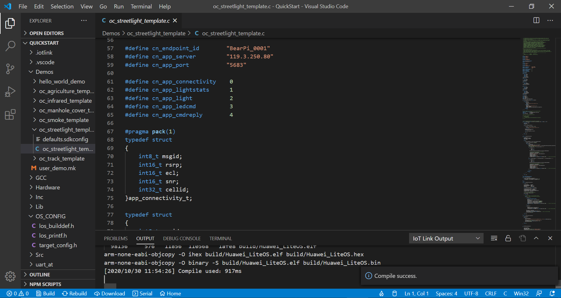
- Use a USB data cable to connect the BearPi development board to the computer. Set the dialing test switch in the upper right corner of the board to the AT-MCU mode.
- Click Download on the toolbar at the bottom of Visual Studio Code and wait until the burning is complete. A message is then displayed, indicating that the burning is successful.
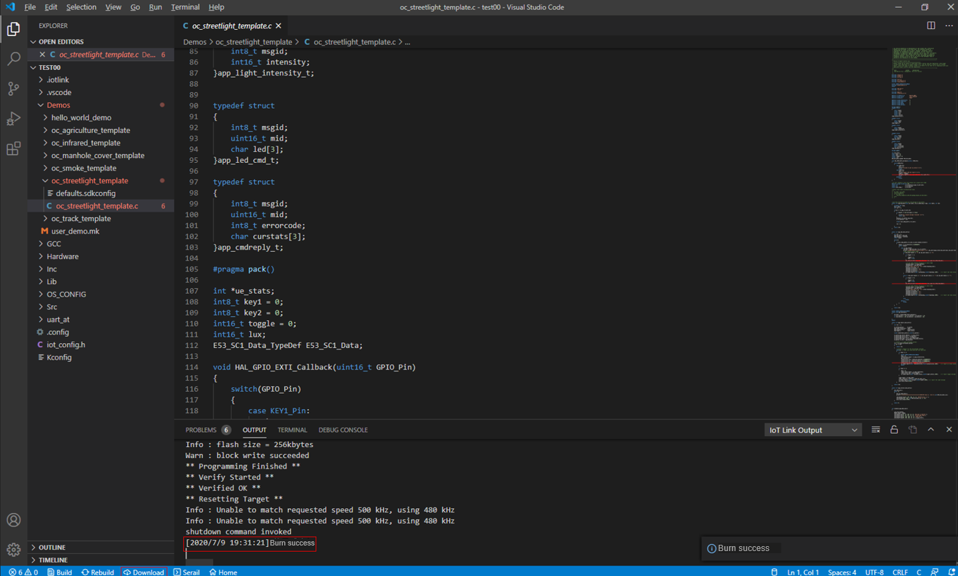

If the burning fails, the possible cause is that the development board does not have a driver and cannot communicate with the computer through the serial port. In this case, perform 2 to check whether the ST-Link driver is installed. If the driver is not installed, download and install the ST-Link driver by following 4.a.
- (Optional) Install the ST-Link driver.
- Visit the ST website, download the ST-Link driver, and double-click the stlink_winusb_install.bat file to start automatic installation. This section uses Windows 10 64-bit ST-Link 2.0.1 as an example.
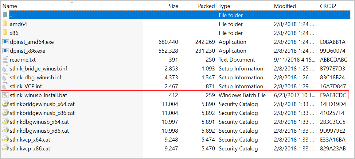
Note: You can also use an EXE file that adapts to your system version to install the driver.
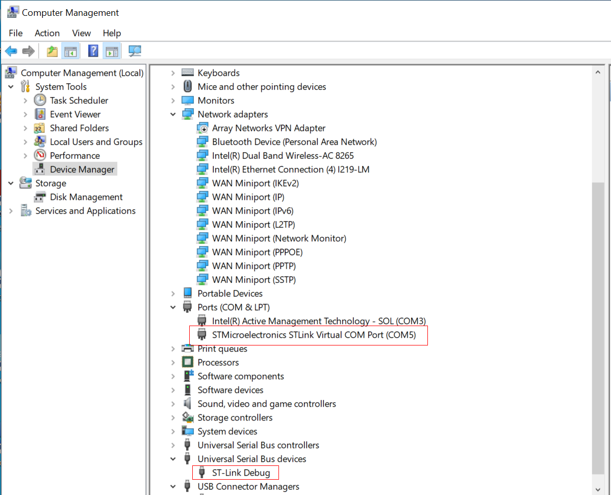
- Open the device manager on the computer to check whether the driver is installed. If the information shown in the following figure is displayed, the driver is installed.
- Visit the ST website, download the ST-Link driver, and double-click the stlink_winusb_install.bat file to start automatic installation. This section uses Windows 10 64-bit ST-Link 2.0.1 as an example.
Locating Module Communication Problems Using AT Commands
When IoT Link is connected to the platform, you can use AT commands to quickly locate the connectivity problem between the module and the cloud. This section describes how to use AT commands to detect common problems of the communications module, for example, the device fails to go online or data fails to be reported.
- Connect the BearPi development board to the computer and ensure that the driver has been installed. Set the dialing test switch in the upper right corner of the board to the AT-PC mode.
- Click Serial on the toolbar at the bottom of Visual Studio Code.

- Select the port number obtained in 2, set Baudrate to 9600, and click Open.
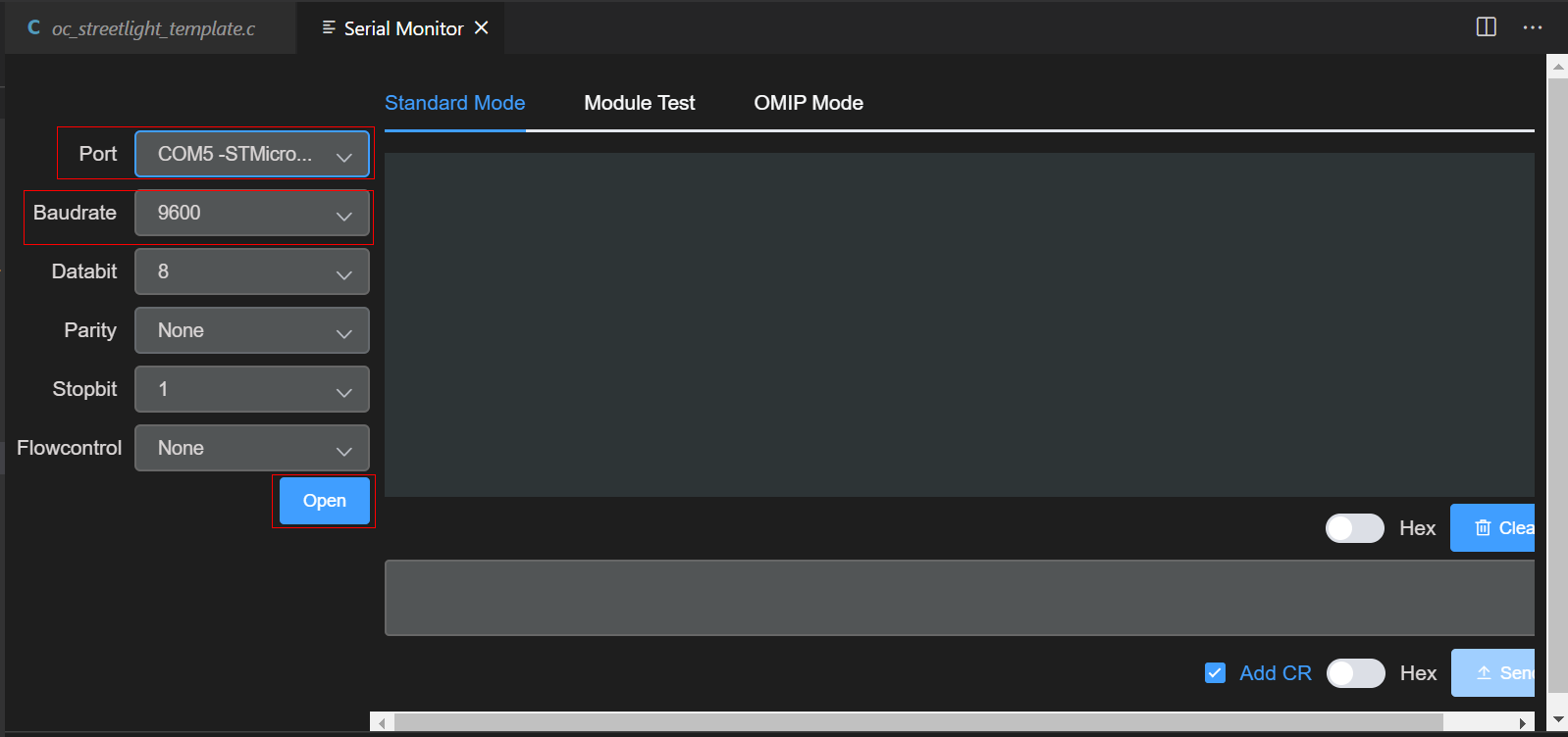
- Enter AT+CGATT? and click Send. If +CGATT:1 is returned, the network attach is successful, indicating that the NB-IoT network is normal. If +CGATT:0 is returned, the network attach fails, indicating that the NB-IoT network is abnormal. In this case, check whether the SIM card is correctly inserted or contact the carrier to check the network status.
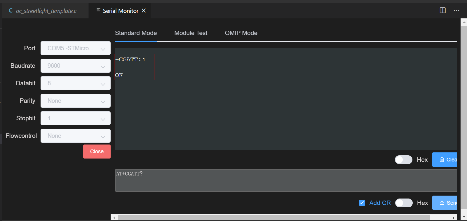

- After using the AT commands to detect the module communication, set the dialing test switch to the AT-MCU mode so that the collected data can be sent to the platform through the communication module after the console configuration.
- In the AT-PC mode, the development board communicates with the serial port of the computer, and AT commands are used to read and write data such as the status of the development board. In the AT-MCU mode, the development board connects to the network through the SIM card inserted into the module to implement NB-IoT communications.
- The AT+CSQ<CR> command is used to check the network signal strength and SIM card status. Enter AT+CSQ<CR> and click Send. +CSQ:**,## is returned. In the preceding output, ** ranges from 10 to 31. A larger value indicates better signal quality. ## indicates the bit error rate, which ranges from 0 to 99. If the returned values are not within these ranges, check whether the antenna or SIM card is correctly installed.
Note: This section lists only two common AT commands for detecting the network status of the module. For more AT commands, see the instructions of the BearPi module.
Operations on the Console
After connecting the physical device and compiling and programming code, go to the IoTDA console to create a product, define a product model, develop a codec, and register the device.
- Creating a product: Specify the protocol type, data format, manufacturer name, and device type of a product on the platform. In this example, create a smart street light product on the console based on the product features.
- Defining a product model: A product model is a JSON file that describes device capabilities. It defines basic device properties and message formats for data reporting and command delivery. Defining a product model is to construct an abstract model of a device in the platform to enable the platform to understand the device properties. In this example, define a street light product model with light switch control, illumination intensity, and signal quality properties on the console.
- Developing a codec: A codec is called by the platform to convert data between the binary and JSON formats. The binary data reported by a device is decoded into the JSON format for the application to read, and the commands delivered by the application are encoded into the binary format for the device to understand and execute. Since the data format of smart street lights is binary, a codec is needed to enable the platform to understand the data reported by the smart street light and to enable the smart street light to understand the commands delivered by the platform.
- Registering the device: Register the BearPi smart street light with the platform.
Creating a Product
A product is a collection of devices with the same capabilities or features. In addition to physical devices, a product includes product information, product models, and codecs generated during IoT capability building. In this example, create a smart street light product on the IoTDA console.
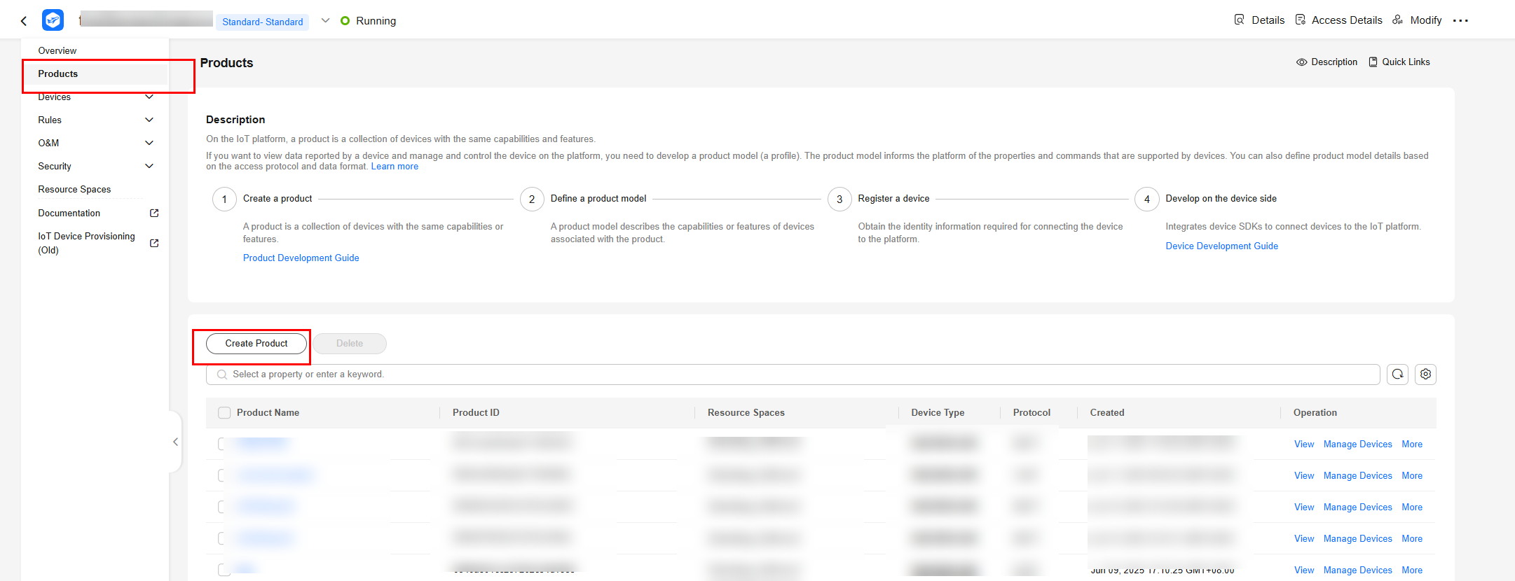
- Log in to the console, choose Products in the navigation pane, and click Create Product on the left.
Figure 5 Creating a product
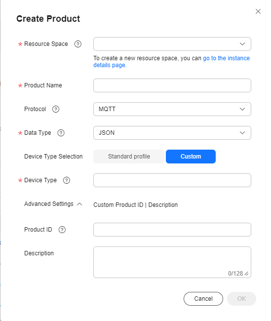
- Create a product whose protocol type is LwM2M or CoAP and device type is StreetLamp, set parameters as prompted, and click OK.
Figure 6 Creating a product - CoAP
Uploading a Product Model
A product model is a JSON file that describes device capabilities. It defines basic device properties and message formats for data reporting and command delivery. Defining a product model is to construct an abstract model of a device in the platform to enable the platform to understand the device function. A developed product model is provided for you to quickly experience the cloud migration process. If you want to go through the process of developing a product model, go to Developing a Product Model.
Procedure
- Click the created product. The product details page is displayed.
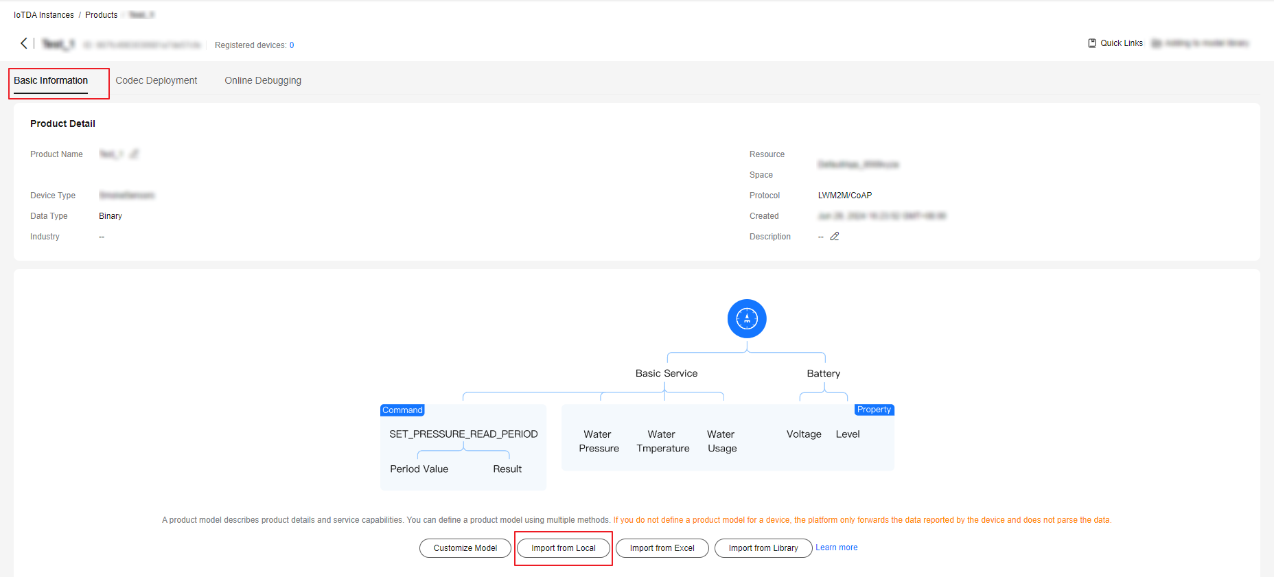
- On the Model Definition tab page, click Import from Local.
Figure 7 Uploading a product model - CoAP
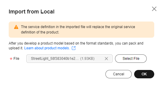
- On the dialog box displayed, upload the product model provided and click OK.
Figure 8 Uploading a model file - CoAP
Registering a Device
This section describes how to register a device integrated with the NB-IoT module, the BearPi smart street light in this example, to the platform.
- On the product details page, click the Online Debugging tab, and click Add Test Device. This section use a non-security NB-IoT device as an example.
- In the dialog box displayed, set the parameters and click OK.
Figure 9 Online debugging - Adding a test device
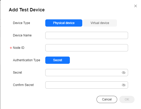
- Device Name: Customize a name.
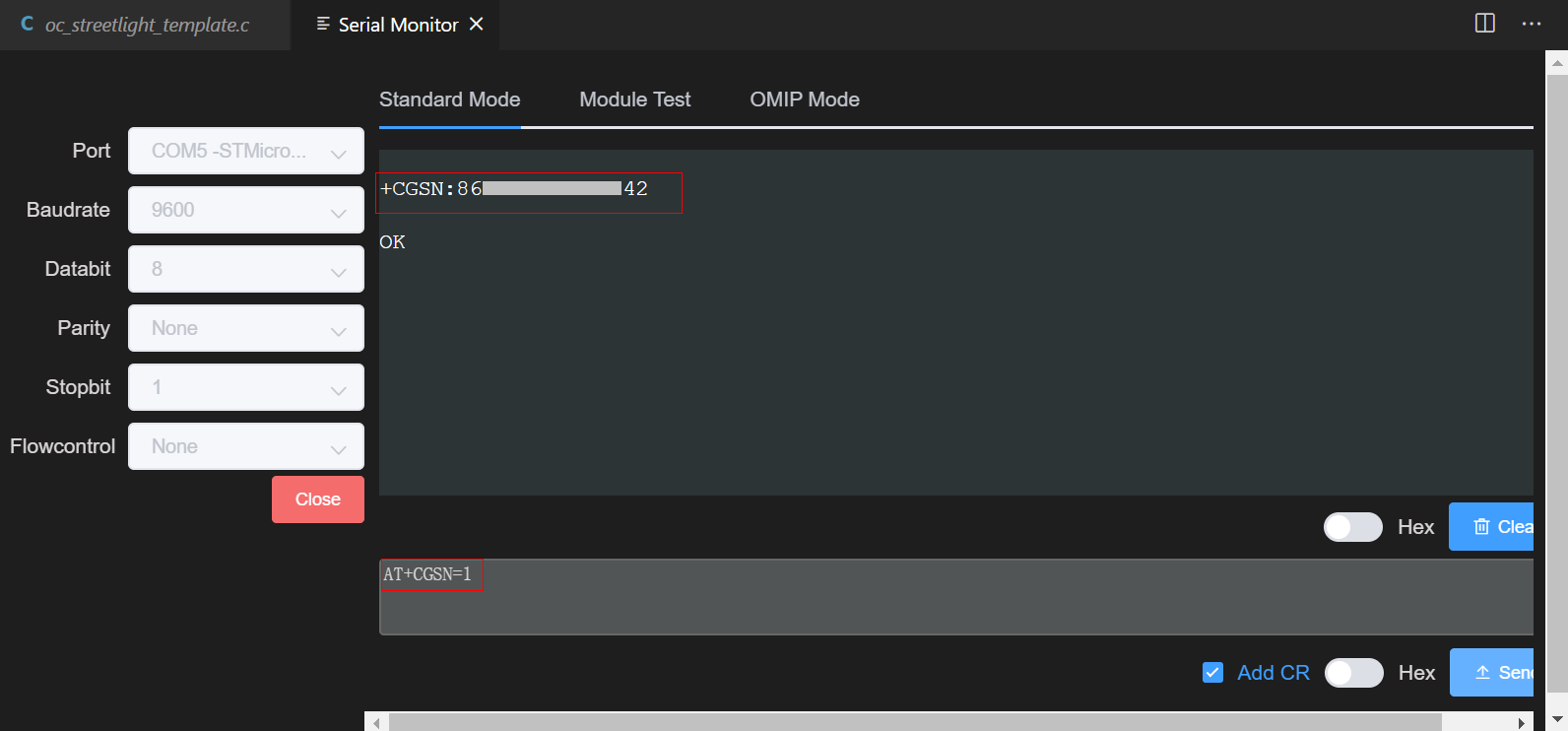
- Node ID: Enter the IMEI of the device. The node ID will be carried by the device for device access authentication. You can view the node ID on the NB-IoT module. You can also set the dialing test switch to the AT-PC mode, select the STM port, set the baud rate to 9600, and run the AT+CGSN=1 command to obtain the IMEI.
Note: After obtaining the IMEI and registering the device, set the dialing test switch of the development board to the AT-MCU mode because the development board connects to the network through the NB-IoT card only in MCU mode.
- Registration Mode: Select Unencrypted.
- The device is created. You can view the created device on the console.
Reporting Data
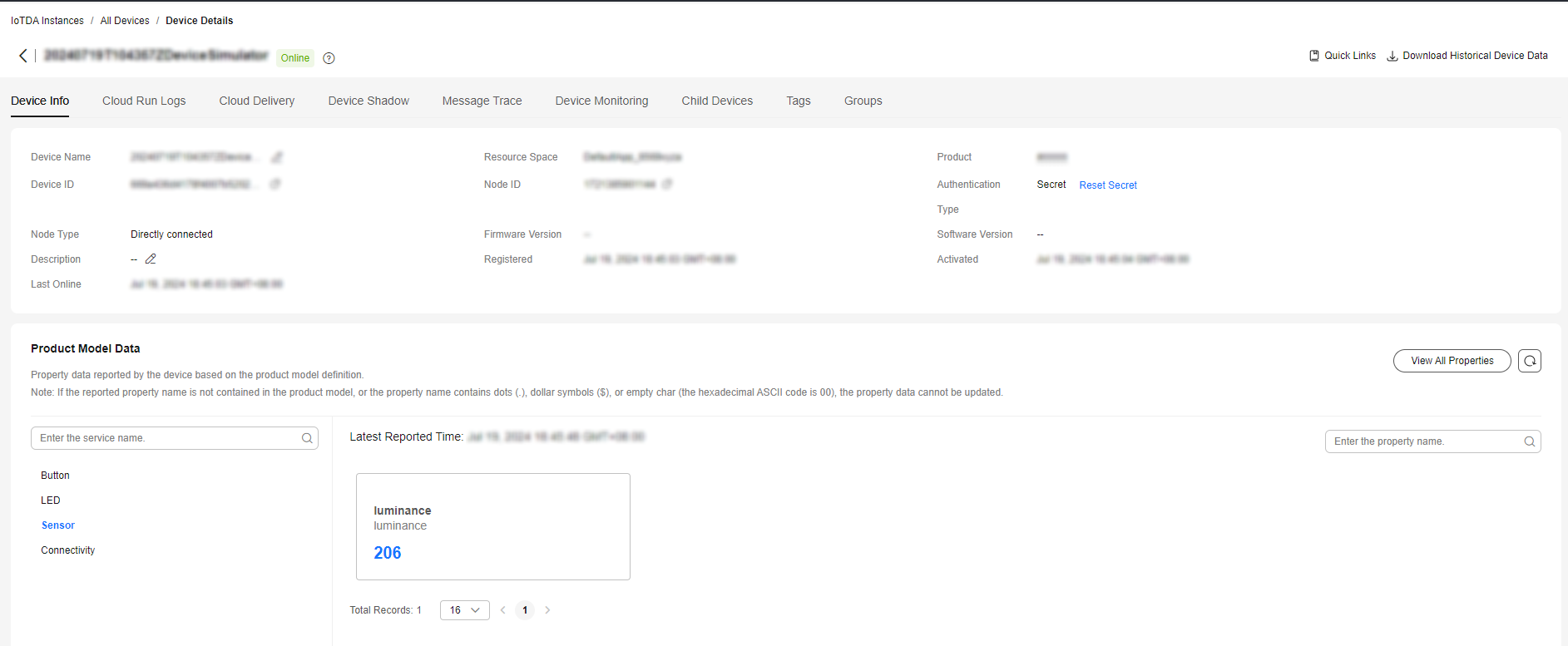
After the connection between the platform and the development board is set up, the BearPi smart street light reports the light sensor data every 2 seconds according to the code burnt to the development board. The reporting frequency can be customized in the demo based on service requirements. You can block the light with your hand to change the light intensity and view the real-time change of the light intensity data reported to the platform.
Note: Ensure that the dialing test switch of the development board is set to the AT-MCU mode.
- Log in to the IoTDA console and click the target instance card. Choose Devices > All Devices.
- Select the target device and click View to check the data reported to the platform.
Figure 10 NB-IoT device data reporting - Viewing data
Delivering a Command
- Log in to the IoTDA console. Click the target product to go to its details page.
- On the Online Debugging tab page, click the target device to access the debugging page.
- After setting the command parameters, click Send.
Figure 11 Command delivery debugging - SmokeDetector
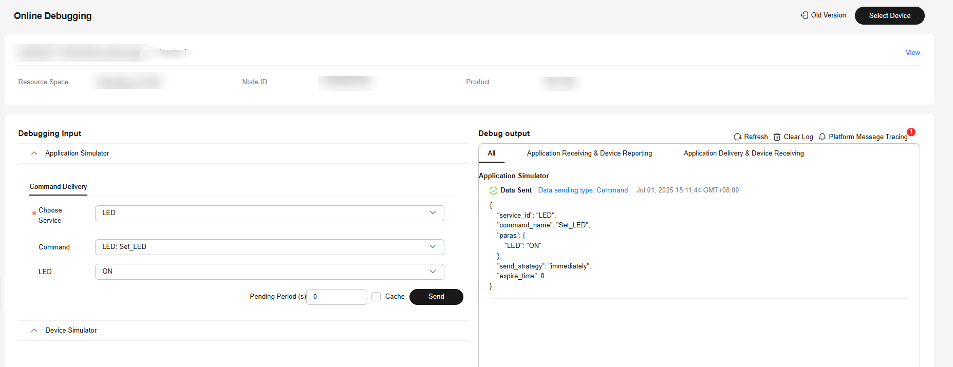
- The light on the BearPi board is on. Deliver the OFF command. The light is turned off.
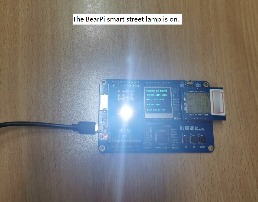
This is the end-to-end development of a smart street light by using the NB-IoT BearPi development board.
Reference
- Developing a Product Model
On the Basic Information tab page, click Customize Model to add services of the product.
Table 1 describes the service defined in the product model.
Table 1 Device service list Service ID
Description
Button
Real-time button detection
LED
LED control
Sensor
Real-time light intensity detection
Connectivity
Real-time signal quality detection
The following table lists the service capabilities.
Table 2 Button Capability Description
Property Name
Data Type
Data Range
Property
toggle
Integer
0 to 65535
Table 3 LED command list Capability Description
Command Name
Command Parameter
Parameter Name
Type
Data Length
Enumeration
Commands
Set_LED
Command
LED
String
3
ON,OFF
Response
Light_state
String
3
ON,OFF
Table 4 Sensor Capability Description
Property Name
Data Type
Data Range
Property
luminance
Integer
0 to 65535
Table 5 Connectivity Capability Description
Property Name
Data Type
Data Range
Properties
SignalPower
Integer
–140 to –44
ECL
Integer
0 to 2
SNR
Integer
–20 to 30
CellID
Integer
0 to 65535
Feedback
Was this page helpful?
Provide feedbackThank you very much for your feedback. We will continue working to improve the documentation.See the reply and handling status in My Cloud VOC.
For any further questions, feel free to contact us through the chatbot.
Chatbot

