
Red de VPC
Definición del modelo
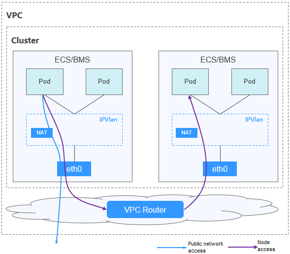
Comunicación de pod a pod
- En el mismo nodo: Los paquetes se reenvían directamente con IPVlan.
- Entre los nodos: Los paquetes se reenvían al gateway predeterminado con las rutas predeterminadas, y luego al nodo par con las rutas de VPC.
Ventajas y desventajas
Ventajas
- No se requiere encapsulación de túnel, por lo que los problemas de red son fáciles de localizar y el rendimiento es alto.
- Las redes externas de una VPC se pueden conectar directamente a las direcciones IP de contenedor.
Desventajas
- El número de nodos está limitado por la cuota de ruta de VPC.
- A cada nodo se le asigna un bloque CIDR de un tamaño fijo, lo que conduce a un desperdicio de direcciones IP en el bloque CIDR de contenedor.
- Los pods no pueden usar directamente funcionalidades como EIP y grupos de seguridad.
Escenarios posibles
- Requisitos de alto rendimiento: como no se requiere encapsulación de túnel, el modelo de red de VPC ofrece un rendimiento cercano al de una red de VPC en comparación con el modelo de red de túnel de contenedor. Por lo tanto, el modelo de red de VPC es aplicable a escenarios que tienen altos requisitos de rendimiento, como el cómputo de IA y el cómputo de big data.
- Redes de la escala pequeña y mediana: La red de VPC está limitada por la cuota de ruta de VPC. Actualmente, se admite un máximo de 200 nodos de forma predeterminada. Si hay requisitos de red a gran escala, puede aumentar la cuota de ruta de VPC.
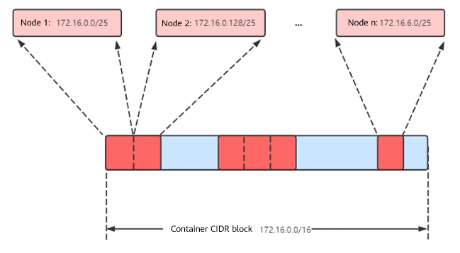
Gestión de direcciones IP de contenedores
La red de VPC asigna direcciones IP de contenedor de acuerdo con las siguientes reglas:
- El bloque CIDR de contenedor se asigna por separado.
- Las direcciones IP se asignan por nodo. Un bloque CIDR con un tamaño fijo (que es configurable) se asigna a cada nodo en un grupo desde el bloque CIDR de contenedor.
- El bloque CIDR de contenedor asigna cíclicamente bloques CIDR a nuevos nodos en secuencia.
- Los pods programados para un nodo se asignan cíclicamente direcciones IP de bloques CIDR asignados al nodo.
Número máximo de nodos que se pueden crear en el clúster usando la red de VPC = Número de direcciones IP en el bloque CIDR de contenedor /Número de direcciones IP en el bloque CIDR asignado al nodo por el bloque CIDR de contenedor
Por ejemplo, si el bloque CIDR de contenedor es 172.16.0.0/16, el número de direcciones IP es 65536. La máscara del bloque CIDR de contenedor asignado al nodo es 25. Es decir, el número de direcciones IP de contenedor en cada nodo es 128. Por lo tanto, se puede crear un máximo de 512 (65536/128) nodos. Además, el número de nodos que se pueden crear en un clúster también depende de la red de nodos y de la escala del clúster.
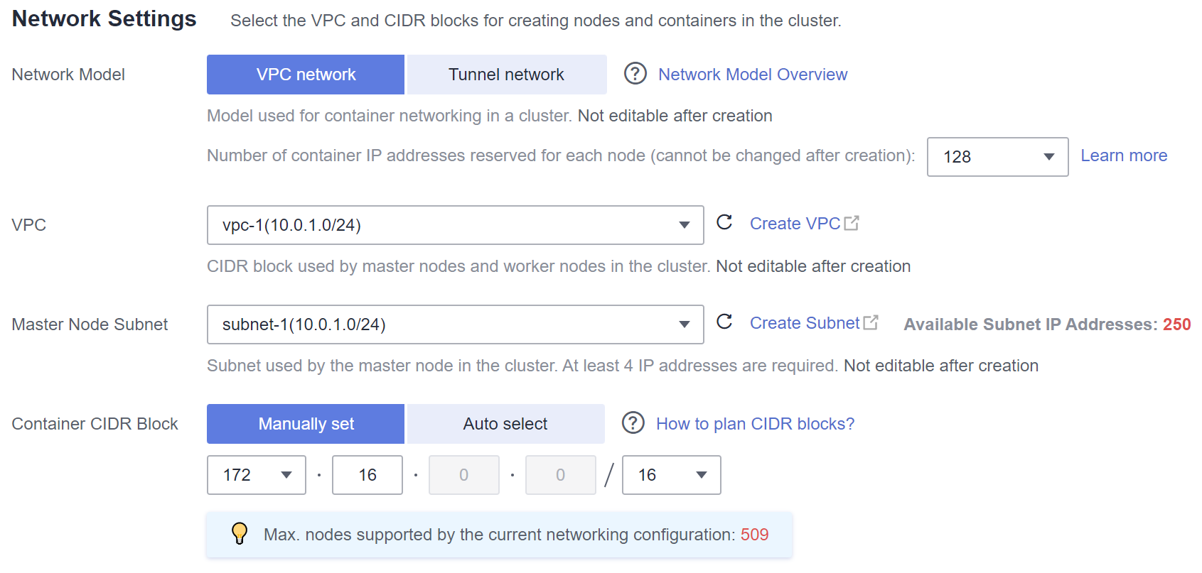
Recomendación para la planificación de bloques CIDR
Como se describe en Estructura de red de clústeres, las direcciones de red de un clúster se pueden dividir en tres partes: red de nodo, red de contenedor y red de servicio. Al planificar direcciones de red, tenga en cuenta los siguientes aspectos:
- Los tres bloques CIDR no pueden superponerse. De lo contrario, se produce un conflicto.
- Asegúrese de que cada bloque CIDR tenga suficientes direcciones IP.
- Las direcciones IP en el bloque CIDR del nodo deben coincidir con la escala del clúster. De lo contrario, no se pueden crear nodos debido a la insuficiencia de direcciones IP.
- Las direcciones IP en el bloque CIDR de contenedor deben coincidir con la escala de servicio. De lo contrario, los pods no se pueden crear debido a la insuficiencia de direcciones IP. El número de pods que se pueden crear en cada nodo también depende de otros parámetros. Para más detalles, consulte Número máximo de pods que se pueden crear en un nodo.
Suponga que un clúster contiene 200 nodos y que el modelo de red es una red VPC.
En este caso, el número de direcciones IP disponibles en la subred de nodo seleccionada debe ser mayor que 200. De lo contrario, no se pueden crear nodos debido a la insuficiencia de direcciones IP.
El bloque CIDR de contenedor es 10.0.0.0/16, y el número de direcciones IP disponibles es 65536. Como se describe en Gestión de direcciones IP de contenedores, a la red de VPC se le asigna un bloque CIDR con el tamaño fijo (utilizando la máscara para determinar el número máximo de direcciones IP de contenedor asignadas a cada nodo). Por ejemplo, si el límite superior es 128, el grupo soporta un máximo de 512 (65536/128) nodos, incluidos los tres nodos maestros.
Ejemplo del acceso a la red de VPC
Cree un clúster mediante el modelo de red de VPC. El clúster contiene un nodo.
$ kubectl get node
NAME           STATUS   ROLES    AGE   VERSION
192.168.0.99   Ready    <none>   9d    v1.17.17-r0-CCE21.6.1.B004-17.37.5
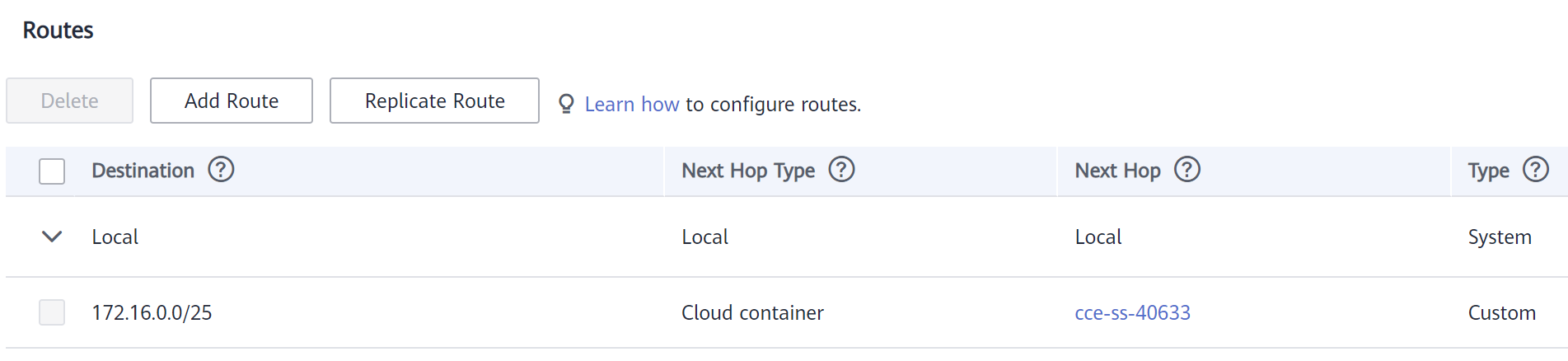
Compruebe la tabla de enrutamiento de VPC. La dirección de destino 172.16.0.0/25 es el bloque CIDR de contenedor asignado al nodo, y el salto siguiente es el nodo correspondiente. Cuando se accede a la dirección IP de contenedor, la ruta de VPC reenvía la solicitud de acceso al nodo de salto siguiente. Esto indica que el modelo de red de VPC utiliza las rutas de VPC.
Cree una Deployment en el clúster.
kind: Deployment
apiVersion: apps/v1
metadata:
  name: example
  namespace: default
spec:
  replicas: 4
  selector:
    matchLabels:
      app: example
  template:
    metadata:
      labels:
        app: example
    spec:
      containers:
        - name: container-0
          image: 'nginx:perl'
      imagePullSecrets:
        - name: default-secret
Revisa el pod.
$ kubectl get pod -owide
NAME                       READY   STATUS    RESTARTS   AGE   IP           NODE           NOMINATED NODE   READINESS GATES
example-86b9779494-l8qrw   1/1     Running   0          14s   172.16.0.6   192.168.0.99   <none>           <none>
example-86b9779494-svs8t   1/1     Running   0          14s   172.16.0.7   192.168.0.99   <none>           <none>
example-86b9779494-x8kl5   1/1     Running   0          14s   172.16.0.5   192.168.0.99   <none>           <none>
example-86b9779494-zt627   1/1     Running   0          14s   172.16.0.8   192.168.0.99   <none>           <none>
En este caso, se puede acceder directamente a la dirección IP del pod desde un nodo fuera del clúster en la misma VPC. Esta es una característica de la función de la red de VPC.
También se puede acceder al pod desde un nodo en el mismo clúster o en el pod. Como se muestra en la siguiente figura, se puede acceder al pod directamente desde el contenedor.
$ kubectl exec -it example-86b9779494-l8qrw -- curl 172.16.0.7
<!DOCTYPE html>
<html>
<head>
<title>Welcome to nginx!</title>
<style>
    body {
        width: 35em;
        margin: 0 auto;
        font-family: Tahoma, Verdana, Arial, sans-serif;
    }
</style>
</head>
<body>
<h1>Welcome to nginx!</h1>
<p>If you see this page, the nginx web server is successfully installed and
working. Further configuration is required.</p>

<p>For online documentation and support please refer to
<a href="http://nginx.org/">nginx.org</a>.<br/>
Commercial support is available at
<a href="http://nginx.com/">nginx.com</a>.</p>

<p><em>Thank you for using nginx.</em></p>
</body>
</html> 


