
Red de túneles de contenedores
Modelo de red de túneles de contenedores
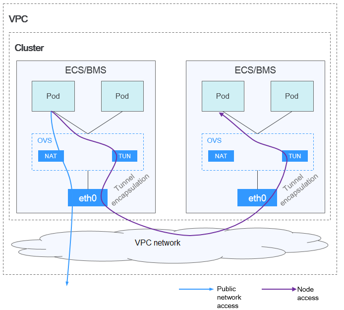
Comunicación de pod a pod
- En el mismo nodo: los paquetes se reenvían directamente a través del puente de OVS en el nodo.
- Entre los nodos: Los paquetes se encapsulan en el puente de OVS y luego se reenvían al nodo del otro extremo.
Ventajas y desventajas
Ventajas
- La red de contenedor está desacoplada de la red de nodos y no está limitada por las cuotas de VPC y la velocidad de respuesta (como el número de rutas de VPC, el número de ENI elásticos y la velocidad de creación).
- Se admite el aislamiento de red. Para obtener más información, véase Network Policies.
- Se admiten límites de ancho de banda.
- Se admite la creación de redes a gran escala.
Desventajas
- Sobrecarga alta de encapsulación, redes complejas y rendimiento bajo
- Error al utilizar las capacidades de balanceo de carga y grupo de seguridad proporcionadas por la VPC
- Las redes externas no se pueden conectar directamente a las direcciones IP de contenedor.
Escenarios posibles
- Bajos requisitos de rendimiento: Como la red de túnel contenedor requiere una encapsulación adicional de túnel VXLAN, tiene entre un 5% y un 15% de pérdida de rendimiento en comparación con los otros dos modelos de red contenedor. Por lo tanto, la red de túnel contenedor es aplicable a escenarios que no tienen requisitos de alto rendimiento, como aplicaciones web y servicios de extremo medio y de extremo medio con un pequeño número de solicitudes de acceso.
- Redes a gran escala: A diferencia de la red de VPC que está limitada por la cuota de ruta de VPC, la red de túnel contenedor no tiene ninguna restricción en la infraestructura. Además, la red de túnel de contenedor controla el dominio de difusión al nivel de nodo. La red de túneles de contenedor admite un máximo de 2000 nodos.
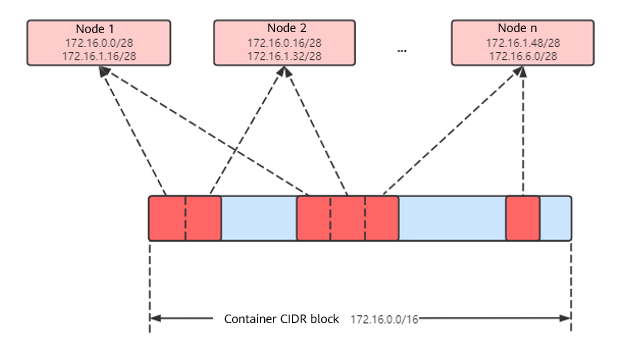
Gestión de direcciones IP de contenedores
La red de túneles contenedor asigna las direcciones IP de contenedor de acuerdo con las siguientes reglas:
- El bloque CIDR de contenedor se asigna por separado, lo que es irrelevante para el bloque CIDR de nodo.
- Las direcciones IP se asignan por nodo. Uno o más bloques CIDR con un tamaño fijo (16 por defecto) se asignan a cada nodo en un grupo desde el bloque CIDR de contenedor.
- Cuando se agotan las direcciones IP de un nodo, puede solicitar un nuevo bloque CIDR.
- El bloque CIDR de contenedor asigna cíclicamente bloques CIDR a los nuevos nodos o los nodos existentes en secuencia.
- Los pods programados para un nodo son direcciones IP asignadas cíclicamente desde uno o más bloques CIDR asignados al nodo.
Número máximo de nodos que se pueden crear en el clúster usando la red de túnel de contenedor = Número de direcciones IP en el bloque CIDR de contenedor / Tamaño del bloque CIDR de IP asignado al nodo por el bloque CIDR de contenedor a la vez (16 por defecto)
Por ejemplo, si el bloque CIDR de contenedor es 172.16.0.0/16, el número de direcciones IP es 65536. Si se asignan 16 direcciones IP a un nodo a la vez, se puede crear un máximo de 4096 (65536/16) nodos en el clúster. Este es un caso extremo. Si se crean 4096 nodos, se puede crear un máximo de 16 pods para cada nodo porque solo se asignan 16 bloques CIDR IP\s a cada nodo. Además, el número de nodos que se pueden crear en un clúster también depende de la red de nodos y de la escala del clúster.

Recomendación para la planificación de bloques CIDR
Como se describe en Estructura de red de clústeres, las direcciones de red de un clúster se pueden dividir en tres partes: red de nodo, red de contenedor y red de servicio. Al planificar direcciones de red, tenga en cuenta los siguientes aspectos:
- Los tres bloques CIDR no pueden superponerse. De lo contrario, se produce un conflicto. Todas las subredes (incluidas las creadas a partir del bloque CIDR secundario) en la VPC donde reside el clúster no pueden entrar en conflicto con los bloques CIDR de contenedor y de Service.
- Asegúrese de que cada bloque CIDR tenga suficientes direcciones IP.
- Las direcciones IP en el bloque CIDR del nodo deben coincidir con la escala del clúster. De lo contrario, no se pueden crear nodos debido a la insuficiencia de direcciones IP.
- Las direcciones IP en el bloque CIDR de contenedor deben coincidir con la escala de servicio. De lo contrario, los pods no se pueden crear debido a la insuficiencia de direcciones IP. El número de pods que se pueden crear en cada nodo también depende de otros parámetros. Para más detalles, consulte Número máximo de pods que se pueden crear en un nodo.
Ejemplo de acceso a la red de túneles de contenedores
Cree un clúster que utilice el modelo de red de túnel de contenedor. Cree una Deployment en el clúster.
kind: Deployment
apiVersion: apps/v1
metadata:
  name: example
  namespace: default
spec:
  replicas: 4
  selector:
    matchLabels:
      app: example
  template:
    metadata:
      labels:
        app: example
    spec:
      containers:
        - name: container-0
          image: 'nginx:perl'
          resources:
            limits:
              cpu: 250m
              memory: 512Mi
            requests:
              cpu: 250m
              memory: 512Mi
      imagePullSecrets:
        - name: default-secret
Vea el pod creado.
$ kubectl get pod -owide
NAME                       READY   STATUS    RESTARTS   AGE     IP          NODE           NOMINATED NODE   READINESS GATES
example-5bdc5699b7-5rvq4   1/1     Running   0          3m28s   10.0.0.20   192.168.0.42   <none>           <none>
example-5bdc5699b7-984j9   1/1     Running   0          3m28s   10.0.0.21   192.168.0.42   <none>           <none>
example-5bdc5699b7-lfxkm   1/1     Running   0          3m28s   10.0.0.22   192.168.0.42   <none>           <none>
example-5bdc5699b7-wjcmg   1/1     Running   0          3m28s   10.0.0.52   192.168.0.64   <none>           <none>
En este caso, no se puede acceder directamente a la dirección IP del pod fuera del clúster en la misma VPC. Esta es una característica de la red de túneles de contenedor.
Sin embargo, se puede acceder al pod desde un nodo en el clúster o en el pod. Como se muestra en la siguiente figura, se puede acceder al pod directamente desde el contenedor.
$ kubectl exec -it example-5bdc5699b7-5rvq4 -- curl 10.0.0.21
<!DOCTYPE html>
<html>
<head>
<title>Welcome to nginx!</title>
<style>
    body {
        width: 35em;
        margin: 0 auto;
        font-family: Tahoma, Verdana, Arial, sans-serif;
    }
</style>
</head>
<body>
<h1>Welcome to nginx!</h1>
<p>If you see this page, the nginx web server is successfully installed and
working. Further configuration is required.</p>

<p>For online documentation and support please refer to
<a href="http://nginx.org/">nginx.org</a>.<br/>
Commercial support is available at
<a href="http://nginx.com/">nginx.com</a>.</p>

<p><em>Thank you for using nginx.</em></p>
</body>
</html> 


