Configuring the Connection Between a DLI Queue and a Data Source on the Internet
Scenario
This section provides instructions to enable network connectivity for DLI queues to be accessed from the Internet. You can configure SNAT rules and add routes to the public network to enable communications between a queue and the Internet.
Procedure

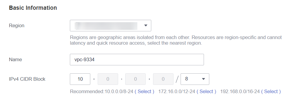
Step 1: Create a VPC
Log in to the VPC console and create a VPC. The created VPC is used for NAT to access the public network.
For details about how to create a VPC, see Creating a VPC.
Step 2: Create a Dedicated Queue
In this example, you will create a pay-per-use queue that uses dedicated resources.

The billing mode of the queue must be Yearly/Monthly or Pay-per-use. (If you select Pay-per-use, select Dedicated Resource Mode after you select a queue type.)
You can only create enhanced datasource connections for yearly/monthly resources or pay-per-use resources in dedicated mode.
- Log in to the DLI management console.
- Click Buy Queue in the upper left corner on the homepage page. On the displayed page, specify specifications and other required parameters.
For details about the parameters for purchasing a queue, see Creating a Queue.
Step 3: Create an Enhanced Datasource Connection Between the Queue and a VPC
- In the navigation pane of the DLI management console, choose Datasource Connections.
- In the Enhanced tab, click Create.
Enter the connection name, select the created queue, VPC, and subnet, and enter the host information (optional).
Figure 3 Creating an enhanced datasource connection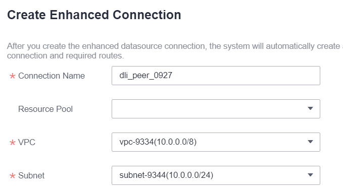
Step 4: Buy an EIP
- Log in to the EIPs page of the network console, click Buy EIP.
- In the displayed page, configure the parameters as required.
For details about how to set the parameters, see Buy EIP.
Step 5: Configure a NAT Gateway
- Create a NAT gateway.
- Log in to the console and search for NAT Gateway in the Service List. The Public NAT Gateways page of the network console is displayed.
- Click Buy Public NAT Gateway and configure the required parameters.
For details, see Buying a Public NAT Gateway.
Figure 4 Buying a NAT gateway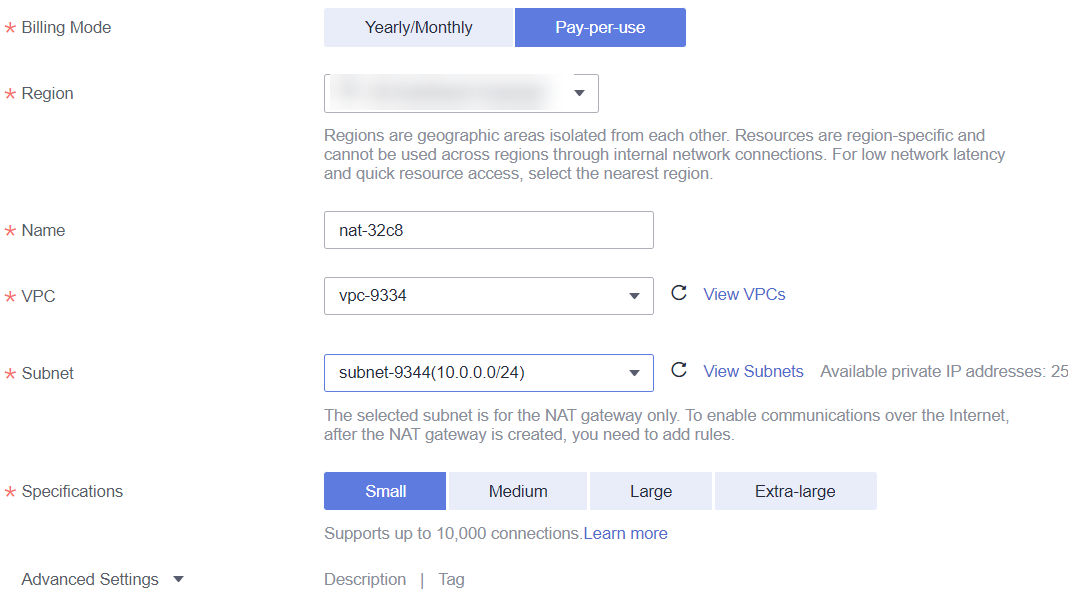
- Click Next, confirm the configurations, and click Submit.
- Add a route.
In the navigation pane on the left of the network console, choose Virtual Private Cloud > Route Tables. After a NAT gateway instance is created, a route to that gateway is automatically created. Click the route table name to view the automatically created route.
The destination address is the public IP address you want to access, and the next hop is the NAT gateway.
Figure 5 Viewing the route
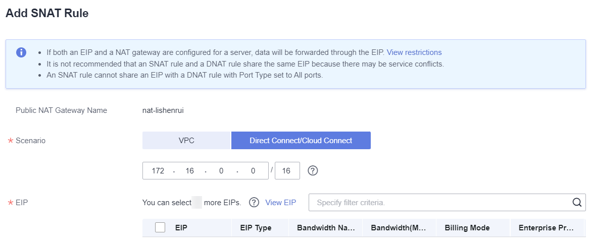
- Add an SNAT rule.
You need to add SNAT rules for the new NAT gateway to allow the hosts in the subnet to communicate with the Internet.
- Click the name of the created NAT gateway on the Public NAT Gateways page of the network console.
- On the SNAT Rules tab, click Add SNAT Rule.
For details, see Adding an SNAT Rule.
- Scenario: Select Direct Connect/Cloud Connect.
- Subnet: Select the subnet where the queue you want to connect locates.
- EIP: Select the target EIP.
Figure 6 Adding an SNAT rule
- Click OK.
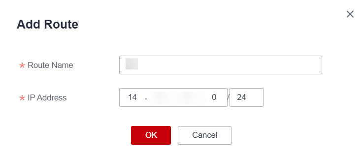
Step 6: Adding a Custom Route
Add a custom route for the enhanced datasource connection you have created. Specify the route information of the IP address you want to access.
For details, see Custom Route Information.
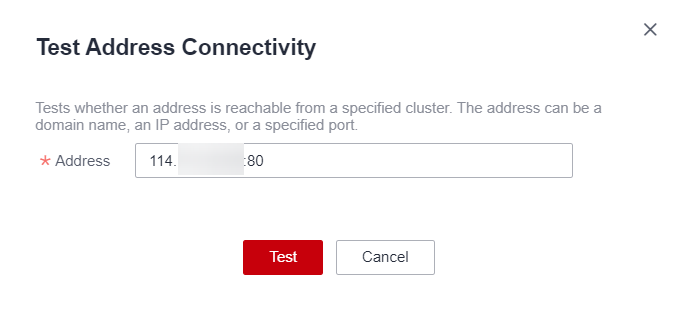
Step 7: Testing the Connectivity to the Public Network
Feedback
Was this page helpful?
Provide feedbackThank you very much for your feedback. We will continue working to improve the documentation.See the reply and handling status in My Cloud VOC.
For any further questions, feel free to contact us through the chatbot.
Chatbot


