
Logical Models
A logical model is an entity relationship diagram that accurately describes business rules based on entities and their relationships. Logical models must ensure the correctness and consistency of the data structure required by services and use a series of standard rules to reflect the features of various objects, and accurately define the relationships between entities.
In addition, logical models provide a reliable reference for constructing physical models and can be converted into physical models. Logical models are key to a successful database design.
The following parts are included in this topic:
- Considerations in Logical Model Design
- Creating a Logical Model
- Creating and Publishing a Logical Entity
- Converting a Logical Model to a Physical Model
- Importing Logical Entities by Reversing a Database
Considerations in Logical Model Design
- You must consider not only the current business status, but also the future business development.
- Personnel who are familiar with the businesses must participate in the modeling. In this way, the business requirements can be fully integrated into the models.
- Converting the logical model to the physical model must be efficient.
- You must consider physical features during physical modeling.
- Each entity, attribute, and relationship must be consistent with the information in the actual business.
Creating a Logical Model
- On the DataArts Studio console, locate a workspace and click DataArts Architecture.
- On the DataArts Architecture page, choose in the left navigation pane.
- On the Logical Models page, click
 to create a logical model. Figure 1 Creating a Logical Model
- In the dialog box displayed, set the parameters and click OK. Figure 2 Configuring the logical model

Table 1 Parameters for creating a logical model Parameter
Description
*Name
Only letters, numbers, and underscores (_) are allowed.
Prefix
Only letters, numbers, and underscores (_) are allowed. Dimension codes must start with letters.
NOTE:Model prefix verification: When a physical (relational) table in ER modeling, fact table in dimensional modeling, or summary table in the data mart is created, modified, or imported, the system checks whether there is a prefix. If there is no prefix, the verification fails. When a reversing operation is performed, the system also checks for a prefix.
Description
A description of the logical model.
- You can perform the following operations on logical models:
- Click Edit on the right of a logical model to modify its parameters.
- Click Delete on the right of a logical model to delete it. Deleted models cannot be recovered. Exercise caution when performing this operation. Models containing tables cannot be deleted.
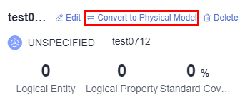
- Click Convert to Physical Model on the right of a logical model to convert it into a physical model. For details, see Converting a Logical Model to a Physical Model.
- Click Logical Entity, Logical Property, or Standard Coverage to go to the logical entity list page and view details about the logical model.
Creating and Publishing a Logical Entity
A logical entity is a logical table. After creating a logical model, you can create a logical entity in the model.
- On the DataArts Architecture page, choose Logical Models in the left navigation pane.
- On the displayed page, click a logical model to access its management page. Then, click Create.
- On the displayed page, configure parameters as prompted.
- Set the basic parameters. Figure 3 Basic settings

Table 2 Parameters on the Basic Settings tab page Parameter
Description
* Subject
Select a subject from the drop-down list box.
Logical Entity Code
You can select Auto Generate or Custom.
* Table Name
Logic entity name.
Newline characters and the following characters are not allowed: \ < > % " ' ;
*Table Code
Name of the physical table converted from the logical entity. Table codes cannot start with numbers. Only letters, numbers, and the following special characters are allowed: _${}
The system can automatically generate the table code through translation based on a configured naming dictionary.
Parent Logical Entity
Set a parent logical entity, which is inherited by child logical entities. Common logical entities and attributes can be logically abstracted as a parent logical entity. After specific attributes are added to the parent logical entity, a child logical entity is generated. The modifications to the attributes in a parent logical entity affect all child logical entities that inherit it.
Tag
Tags are custom identifiers that help you classify and search for data assets. After adding a tag, you can search for related data assets in the DataArts Catalog module with ease.
Click
 . In the dialog box displayed, select one or more existing tags, or enter a new tag name and press Enter. You can also go to the Tags page of the DataArts Catalog module to add a tag. Then, return to this page and select the newly added tag from the drop-down list box. For details, see Managing Asset Tags.
If you want to modify the tag of a table in ER modeling, you must suspend the table first. After modifying the tag, you can publish the table again.
Owner
You can enter an owner name or select an existing owner.
* Description
A description of the table to create. It allows 1 to 200 characters.
- On the Logical Entity Attributes page, add required attributes. Table 3 lists the parameters for logical entity attributes. Figure 4 Adding a logical entity attribute

Table 3 Parameters for logical entity attributes Parameter
Description
*Field Name
Newline characters and the following characters are not allowed: \ < > % " ' ;
*Field English Name
Only letters, numbers, and underscores (_) are allowed. A field code must start with a letter.
*Code
Code of the logical attribute. If the logical entity uses a custom code, the code of the logical attribute can be customized or automatically generated.
Data Type
Data type of the attribute. If you cannot find a desired data type from the drop-down list box, you can add a data type by referring to Field Types.
Data Standard
If you have created data standards, click
 to select one to associate with the logical entity attribute. If Create Data Quality Jobs is selected for Model Design Process on the Function Settings tab page in Configuration Center and a logical entity attribute is associated with a data standard, a quality job is automatically generated after a logical entity attribute is published. A quality rule is generated for each logical entity attribute associated with the data standard. The quality of the logical entity attribute is monitored based on the data standard. You can access the Quality Job page of DataArts Quality to view the job details.
If no data standard is available, create one. See Creating Data Standards for details.
NOTE:- After a logical entity is published, if the data standard code is modified, you must synchronize the dimension tables of the data standard to DataArts Catalog. Otherwise, the data standard code in the logical entity details cannot be updated.
Primary Key
If this parameter is selected, the attribute is a primary key.
NOTE:If you want to convert a logical model into a physical model, note the following restrictions for this parameter:
If an MRS Spark connection is used to connect to MRS Hudi data sources, data can be written to the database only if fields have primary keys. Otherwise, table synchronization fails.
Partition
If this parameter is selected, the attribute is a partition field.
Not Null
Whether the parameter value can be left empty.
Tag
You can click
 to add a tag for the logical entity attribute.
- In the dialog box displayed, select one or more existing tags. If no tag has been added, you can go to the Tags page of the DataArts Catalog module to add a tag. For details, see Managing Asset Tags.
- In the dialog box displayed, enter a new tag name and press Enter. Tag names can contain letters, numbers, and underscores (_), but cannot start with underscores (_).
Security Level
You can click
 to add a security level for the logical entity attribute.
If you cannot find the security level you want, click go to to go to the DataArts Security console and create a security level.
You can disable this function on the Models tab page on the Configuration Center page.
Description
A description of the table to create.
- On the Relationships tab page, click Add to create a relationship.
A relationship refers to the association between a parent and a child entity (also called a primary and a secondary entity). It describes how an entity is associated with another entity, or the impact of an entity's behavior on another entity. Relationships between entities in a data model are particularly important and must be accurately defined. Otherwise, the actual business rules cannot be accurately described in the data model, and data consistency is greatly damaged.
For example, if the student ID attribute of a score table is the primary key for a student table, the relationship between the two tables designed according to the third normal form (3NF) is as follows:- Child logical entity: score table
- Child logical entity attribute FK: student ID
- Child to parent:

- Parent logical entity: student table
- Parent logical entity attribute PK: student ID
- Parent to child:

Figure 5 Adding a relationship
Table 4 Parameters on the Relationships tab page Parameter
Description
Name
Name of the relationship
Child Logical Entity
Select a child logical entity from the drop-down list box. Click
 to set the current logical entity as a child logical entity.
For example, if the student ID attribute of a score table is the primary key for a student table, the child logical entity is the score table, and the corresponding parent logical entity is the student table.
Child Logical Entity Attribute FK
Foreign key of the child logical entity attribute. The attribute of the child logical entity must be the foreign key of the parent logical entity.
For example, if the student ID attribute of a score table is the primary key for a student table, the foreign key of the child logical entity attribute is the student ID in the score table.
Child to Table
 indicates that each piece of data in the child logical entity corresponds to only one piece of data in the parent logical entity.
 indicates that each piece of data in the child logical entity corresponds to at most one piece of data in the parent logical entity.
 indicates that one piece of data in the child logical entity corresponds to multiple pieces of data in the parent logical entity.
 indicates that one piece of data in the child logical entity corresponds to one piece of data in the parent logical entity at least.
Parent to Child
 indicates that the data in the parent logical entity is in one-to-one relationship with the data in the child logical entity.
 indicates that each piece of data in the parent logical entity corresponds to at most one piece of data in the child logical entity.
 indicates that one piece of data in the parent logical entity corresponds to multiple pieces of data in the child logical entity.
 indicates that each piece of data in the parent logical entity corresponds to at least one piece of data in the child logical entity.
Parent Logical Entity
Select a logical entity that has a logical relationship with the selected child logical entity.
For example, if the student ID attribute of a score table is the primary key for a student table, the parent logical entity is the student table, and the corresponding child logical entity is the score table.
Parent Logical Entity Attribute PK
Primary key of the parent logical entity attribute. The attribute of the parent logical entity must be the primary key of the parent logical entity.
For example, if the student ID attribute of a score table is the primary key for a student table, the primary key of the parent logical entity attribute is the student ID in the student table.
Role
You can customize a role name to identify the relationship.
Operation
Click
 to delete a relationship. Click
  to edit the relationship.
 - On the Mappings page, click Create to create a mapping. Then click Save. Mapping means setting up a mapping relationship between the source and destination logical entity. Figure 6 Creating a mapping

- Mapping is automatically generated when a mapping is created. You can change the value.
- Source Logical Entity: If data comes from multiple logical entities of a model, you can click
 next to a logical entity to establish a JOIN relationship between the logical entity and another logical entity. Figure 7 Setting the JOIN condition for the source table
Table 5 JOIN conditions Parameter
Description
*Joined Logical Entity
Select a logical entity for which you want to establish a JOIN relationship with the source logical entity.
Joined Mode
Left JOIN, right JOIN, inner JOIN, and outer JOIN are represented from left to right.
*Joined Attribute
Generally, the JOIN attribute in the source logical entity is the same as that in the joined logical entity. You can click
 or
or  to add or delete a JOIN attribute. The relationship between JOIN attributes is AND.
 - Logical Attribute Mapping: Select a source attribute with the same meaning as the current attribute.
- Set the basic parameters.
- Click Publish, select a reviewer, and click Submit.

In enterprise mode, you can choose to publish the table to the production or development environment. By default, it is published to the production environment. If you do not choose an environment, the logical model cannot be published.
If you select multiple reviewers, the status of the lookup table changes to Published only after all reviewers have approved the publishing application. If any reviewer rejects the application, the status is Rejected.
Wait for the reviewer to approve the application. After the application is approved, return to the model list and view the created logical entity in the list.
By default, Synchronize logical assets is selected for Model Design Process on the Functions tab page of the Configuration Center page.
- For new logical entities, you can click Publish to synchronize them to the logical assets of the DataArts Catalog module.
- For historical logical entities, you can click More and select Synchronize from the drop-down list box to synchronize them to the logical assets in the DataArts Catalog module.
Converting a Logical Model to a Physical Model
After a logical model is created, you can convert it to an existing physical model.
- On the DataArts Studio console, locate a workspace and click DataArts Architecture.
- On the DataArts Architecture page, choose Logical Models in the left navigation pane.
- Find the required logical model and click the conversion button on the model. Logical models can only be converted into a relational model. Figure 8 Converting a logical model to a physical model
- In the Convert to Physical Model dialog box, set the parameters and click OK. Figure 9 Convert to Physical Model dialog box

When a logical model is converted into a physical model, the system checks for a prefix.
Table 6 Parameters Parameter
Description
*Model Name
The name of the physical model to be converted from a logical model. Select a model from the drop-down list box.
*Update Existing Table
This parameter is displayed when a model name is selected.
*Data Connection Type
Select a data connection type from the drop-down list box.
Data Connection
The name of the data connection. Select the required data connection. You are advised to use the same data connection for an ER model.
If no data connection is available, access Management Center to create one. For details, see Configuring DataArts Studio Data Connection Parameters.
Database
The name of the database. Select a database from the drop-down list box. If no database is available, access DataArts Factory to create one. For details, see Creating a Database.
Select Logical Entity
- All: Convert all logical entities into physical tables.
- Partial: Convert the selected logical entities into physical tables.
Queue
DLI queue. This parameter is available only for DLI data connections.
Schema
Schema of DWS or POSTGRESQL. This parameter is available only for DWS and PostgreSQL data connections.
Description
A description of the model. Up to 600 characters are supported.
Importing Logical Entities by Reversing a Database
By reversing databases, you can import one or more created database tables from other data sources into a logical entity directory to turn them into logical entities.
- On the DataArts Architecture console, choose Logical Models in the left navigation pane. Click a logical model to go to the logical entity list page.
- Above the logical entity list, click Reverse Database.
- In the displayed dialog box, set required parameters and click OK.
Table 7 Parameters for reversing the database Parameter
Description
*Subject
Select a subject from the drop-down list.
*Data Connection Type
The data connection types supported by the reverse database are displayed in the drop-down list box. Select the required data connection type.
*Data Connection Name
Select a data connection.
If you want to reverse a database from other data sources to a logical entity directory, you must create a data connection in Management Center to connect to the data source. For details on how to create data connections, see Configuring DataArts Studio Data Connection Parameters.
*Database
Select a database.
*Schema
Select a value from the drop-down list box. This parameter is available only for DWS and PostgreSQL tables.
Queue
DLI queue. This parameter is available only when Data Connection Type is set to DLI.
Update Table
When Yes is selected, if the name of the reversed table is the same as that of an existing table in the logical entity list, the logical entity is updated.
Name Source
Source of the table name or field name after the reverse. The value can be Description or English name. If no description is specified for a table or field, the English name is used.
- Description
- English name NOTE:
If you select Description, field comments of a table must be unique.
*Data Table
You can select All or Partial.
Figure 10 Reverse Database dialog box
- You can view the result on the Last Reverse tab page. If the reverse operation is successful, click Close. If the reverse operation fails, you can view the failure cause. After the fault is rectified, select the table again and click Reverse to retry. Figure 11 Last Reverse tab page

Importing Logical Entities
Importing an Excel file
- Above the logical entity list, click Import and select Import EXCEL. In the Import Table dialog box, click the Import tab and then ER Modeling Template. Figure 12 Importing an Excel file

- Edit and save the downloaded template.
- Choose whether to update existing data.
If a code in the template already exists in the system, the data is considered duplicate.
- No: If the data to be imported already exists in the system, the existing data in the system will not be replaced.
- Yes: If the data to be imported already exists in the system:
- If the existing data in the system is in draft state, the data will be replaced and new draft data will be generated.
- If the existing data in the system is in published state, expanded data will be generated.
- Click Select File and select the template you have edited and saved.
- Click Upload. When the template is uploaded, the Last Import page is displayed. You can view the imported data.
- Click Close to exit the page.
Importing an LDM model
- Before importing an LDM model, select a theme. Otherwise, the model cannot be imported.
- Logical models can be imported.
- Prepare an .ldm logical model exported from the third-party system Power Designer in advance.
- LDM models of version 16.x can be imported.
- Above the logical entity list, click Import and select Import LDM. In the Import Table dialog box, click the Import tab. Figure 13 Importing an LDM model

- Choose whether to update existing data.
- No: If the data to be imported already exists in the system, the existing data in the system will not be replaced.
- Yes: If the data to be imported already exists in the system:
- If the existing data in the system is in draft state, the data will be replaced and new draft data will be generated.
- If the existing data in the system is in published state, expanded data will be generated.
- Click Select File and select the prepared .ldm logical model.
- Click Upload. When the template is uploaded, the Last Import page is displayed. You can view the imported data.
- Click Close to exit the page.
Exporting Logical Entities
More Operations on Logical Entities
- Synchronizing logical entities
In the logical entity list, select logical entities, click Synchronize above the list, and click OK. This operation can be performed only on published tables.
After a logical entity is associated with a quality rule and published, you can click Synchronize Subjects from DataArts Architecture as Directories on the Quality Jobs page on the DataArts Quality console. The quality jobs automatically generated in DataArts Architecture will be synchronized to the corresponding directories in DataArts Quality based on the subject structure.
- Publishing logical entities In the logical entity list, select logical entities and click Publish above the list or in the Operation column. In the displayed dialog box, select a reviewer and click Submit. The logical entities will be published when the publishing request is approved.
In enterprise mode, you can choose to publish the table to the production or development environment. By default, logical entities are published to the production environment. If you do not choose an environment, logical entities cannot be published.
If you select multiple reviewers, the logical entities will be published only after all reviewers have approved the publishing request. If any reviewer rejects the request, the logical entities will not be published.
If you select Auto-review, the request will be automatically approved. This function is for trial use only and not recommended.
- Suspending logical entities
In the logical entity list, select logical entities and click Suspend above the list or click More in the Operation column and select Suspend. This operation can be performed only on published tables.
- Changing the subject of a logical entity
In the logical entity list, select a logical entity and click Change Subject above the list to change the subject of the logical entity.
- Deleting a logical entity
In the logical entity list, select logical entities and click Delete above the list to delete them. This operation can be performed only on draft, rejected, and suspended jobs.
- Adding a tag to a logical entity
In the logical entity list, select a logical entity and click Tag above the list. In the displayed dialog box, add a tag and click OK.
Enter your text and press Enter to temporarily add a tag. A tag can be created only after the information on the entire page is submitted. A maximum of 20 tags can be added.
Logical entities can be queried in fuzzy mode by tag.
- Editing a logical entity
In the logical entity list, locate a logical entity and click Edit in the Operation column. To associate the logical entity with a quality rule, click Associate Quality Rule, set parameters of the quality rule on the displayed page, and click OK.
- Viewing the publishing history
In the logical entity list, locate a logical entity, click More in the Operation column, and select View History to view the publishing history and version comparison of the logical entity.
- Previewing SQL information of a logical entity
In the logical entity list, locate a logical entity, click More in the Operation column, and select Preview SQL to preview the SQL information of the logical entity.
Feedback
Was this page helpful?
Provide feedbackThank you very much for your feedback. We will continue working to improve the documentation.


