
From TaurusDB to TaurusDB (Dual-Active DR)
Supported Source and Destination Databases
| Service database | DR Database |
|---|---|
| TaurusDB Enterprise Edition and Standard Edition | TaurusDB Enterprise Edition and Standard Edition |

Only whitelisted users can use this function.
Database Account Permission Requirements
To start a DR task, the service and DR database users must meet the requirements in the following table. Different types of DR tasks require different permissions. For details, see Table 2. DRS automatically checks the database account permissions in the pre-check phase and provides handling suggestions.
| Type | Permission Required |
|---|---|
| Service database user | The user must have the following permissions: SELECT, CREATE, ALTER, DROP, DELETE, INSERT, UPDATE, TRIGGER, REFERENCES, SHOW VIEW, EVENT, INDEX, LOCK TABLES, CREATE VIEW, CREATE ROUTINE, ALTER ROUTINE, CREATE USER, RELOAD, REPLICATION SLAVE, REPLICATION CLIENT, and WITH GRANT OPTION The root account of the TaurusDB instance has the preceding permissions by default. |
| DR database user | The user must have the following permissions: SELECT, CREATE, ALTER, DROP, DELETE, INSERT, UPDATE, TRIGGER, REFERENCES, SHOW VIEW, EVENT, INDEX, LOCK TABLES, CREATE VIEW, CREATE ROUTINE, ALTER ROUTINE, CREATE USER, RELOAD, REPLICATION SLAVE, REPLICATION CLIENT, and WITH GRANT OPTION The root account of the TaurusDB instance has the preceding permissions by default. |
- You are advised to create an independent database account for DRS task connection to prevent task failures caused by database account password modification.
- After changing the account passwords for the service and DR databases, modify the connection information of the DRS task by referring to Modifying Connection Information to prevent automatic retry after a task failure. Automatic retry will lock the database accounts.
- Table 2 lists the minimum permissions required by a DRS task. If you need to migrate the grant permission through a DRS task, ensure that the connection account of the DRS task has the corresponding permission. Otherwise, the destination database user may not be authorized due to grant execution failure. For example, if the connection account of the DRS task does not require the process permission, but you need to migrate the process permission through a DRS task, ensure that the connection account of the DRS task has the process permission.
Prerequisites
- You have logged in to the DRS console.
- Your account balance is greater than or equal to $0 USD.
- For details about the supported DB types and versions, see Supported Databases.
- If a subaccount is used to create a DRS task, ensure that an agency has been added. To create an agency, see Agency Management.
Suggestions

- During the DR initialization, do not perform DDL operations on the service database. Otherwise, the task may be abnormal.
- During DR initialization, ensure that no data is written to the DR database to ensure data consistency before and after DR.
- The success of DR depends on environment and manual operations. To ensure a smooth DR, perform a DR trial before you start the DR task to help you detect and resolve problems in advance.
- It is recommended that you start your DR task during off-peak hours to minimize the impact on your services.
- If the bandwidth is not limited, initialization of DR will increase query workload of the source database by 50 MB/s and occupy 2 to 4 vCPUs.
- To ensure data consistency, tables without a primary key may be locked for 3s during disaster recovery.
- The data in the DR process may be locked by other transactions for a long period of time, resulting in read timeout.
- If DRS concurrently reads data from a database, it will use about 6 to 10 sessions. The impact of the connections on services must be considered.
- If you read a table, especially a large table, during DR, the exclusive lock on that table may be blocked.
- For more information about the impact of DRS on databases, see How Does DRS Affect the Source and Destination Databases?
- Data-Level Comparison
To obtain accurate comparison results, start data comparison at a specified time point during off-peak hours. If it is needed, select Start at a specified time for Comparison Time. Due to slight time difference and continuous operations on data, data inconsistency may occur, reducing the reliability and validity of the comparison results.
Precautions
Before creating a DR task, read the following precautions:
| Type | Restrictions |
|---|---|
| Disaster recovery objects |
|
| Service database configuration |
|
| DR database configuration |
|
| Precautions |
|
Procedure
- On the Disaster Recovery Management page, click Create Disaster Recovery Task.
- On the Create Disaster Recovery Instance page, select a region and project, specify the task name, description, and the DR instance details, and click Create Now.
- Task information description
Table 4 Task and recipient description Parameter
Description
Region
The region where your service is running. You can change the region.
Task Name
The task name must start with a letter and consist of 4 to 50 characters. It can contain only letters, digits, hyphens (-), and underscores (_).
Description
The description consists of a maximum of 256 characters and cannot contain special characters !=<>'&"\
- DR instance information Figure 1 DR instance information
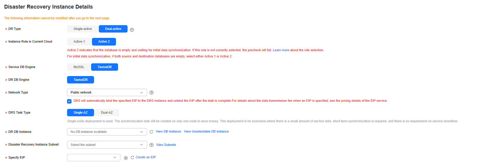
Table 5 DR instance settings Parameter
Description
DR Type
Select Dual-active.
The DR type can be single-active or dual-active. If Dual-active is selected, two subtasks are created by default, a forward DR task and a backward DR task.
NOTE:Only whitelisted users can use dual-active DR. To use this function, submit a service ticket. In the upper right corner of the management console, choose Service Tickets > Create Service Ticket to submit a service ticket.
Current Cloud RDS Instance Role
Select Active 1 or Active 2. This parameter specifies the role of the current RDS DB instance in the DR relationship and is available when DR Type is set to Dual-active. For details about how to choose active 1 and 2, see How Do I Select Active Database 1 and 2 for Dual-Active DR?
- Active 1: Initial data is available on the current cloud database when a task is created.
- Active 2: The instance on the current cloud is empty when a task is created.
Active 2 is used as an example.
Service DB Engine
Select TaurusDB.
DR DB Engine
Select TaurusDB.
Network Type
The public network is used as an example.
Available options: VPN or Direct Connect and Public network. By default, the value is Public network.
DR DB Instance
The TaurusDB instance you created.
Disaster Recovery Instance Subnet
Select the subnet where the disaster recovery instance is located. You can also click View Subnets to go to the network console to view the subnet where the instance resides.
By default, the DRS instance and the DR DB instance are in the same subnet. You need to select the subnet where the DRS instance resides and ensure that there are available IP addresses. To ensure that the disaster recovery instance is successfully created, only subnets with DHCP enabled are displayed.
Specify EIP
This parameter is available when you select Public network for Network Type. Select an EIP to be bound to the DRS instance. DRS will automatically bind the specified EIP to the DRS instance and unbind the EIP after the task is complete. The number of specified EIPs must be the consistent with that of DB instances.
- Specifications Figure 2 Specifications
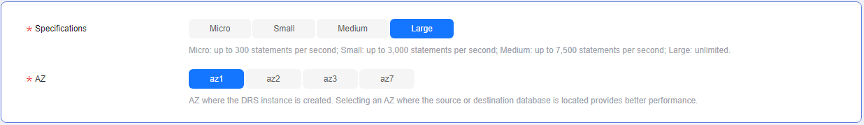
Table 6 Specifications Parameter
Description
Specifications
DRS instance specifications. Different specifications have different performance upper limits. For details, see Real-Time DR.
NOTE:DRS allows you to upgrade specifications only for real-time DR tasks from MySQL to MySQL, from MySQL to TaurusDB, and from TaurusDB to TaurusDB. Task specifications cannot be downgraded. For details, see Changing Specifications.
AZ
Select the AZ where you want to create the DRS task. Selecting the one housing the source or destination database can provide better performance.
- Enterprise Project and Tags
Table 7 Enterprise Project and Tags Parameter
Description
Enterprise Project
An enterprise project you would like to use to centrally manage your cloud resources and members. Select an enterprise project from the drop-down list. The default project is default.
To customize an enterprise project, click Enterprise in the upper right corner of the console. The Enterprise Project Management Service page is displayed. For details, see Creating an Enterprise Project in Enterprise Management User Guide.
Tags
- Tags a task. This configuration is optional. Adding tags helps you better identify and manage your tasks. Each task can have up to 20 tags.
- After a task is created, you can view its tag details on the Tags tab. For details, see Tag Management.
If a task fails to be created, DRS retains the task for three days by default. After three days, the task automatically stops.
- Task information description
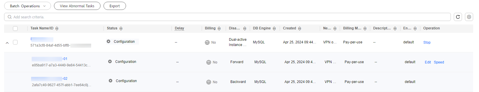
- On the Disaster Recovery Management page, after the task is created, locate the forward subtask and click Edit in the Operation column. The Configure Source and Destination Databases page is displayed. Figure 3 DR task list
- On the Configure Source and Destination Databases page, wait until the DR instance is created. Then, specify source and destination database information and click Test Connection for both the source and destination databases to check whether they have been connected to the DR instance. After the connection tests are successful, select the check box before the agreement and click Next. Figure 4 Service database information
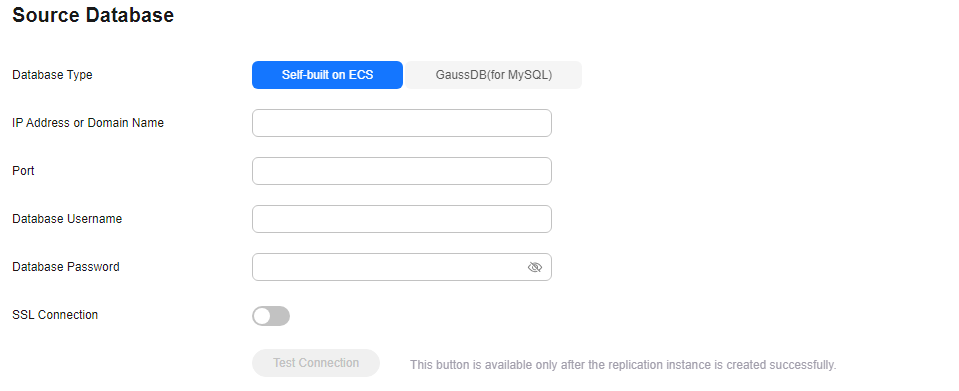
Table 8 Service database settings Parameter
Description
Database Type
By default, Self-built on ECS is selected.
The source database can be a Self-built on ECS or TaurusDB database. After selecting TaurusDB, select the region where the source database resides and the region cannot be the same as the region where the destination database resides. The region where the destination database is located is the region where you log in to the management console. To use the TaurusDB option, submit a service ticket.
IP Address or Domain Name
The IP address or domain name of the service database.
Port
The port of the service database. Range: 1 – 65535
Database Username
The username for accessing the service database.
Database Password
The password for the service database username. You can change the password if necessary. To change the password, perform the following operation after the task is created:
If the task is in the Starting, Initializing, Disaster recovery in progress, or Disaster recovery failed status, in the Connection Information area on the Basic Information tab, click Modify Connection Details. In the displayed dialog box, change the password.
SSL Connection
SSL encrypts the connections between the source and destination databases. If SSL is enabled, upload the SSL CA root certificate.
NOTE:- The maximum size of a single certificate file that can be uploaded is 500 KB.
- If SSL is disabled, your data may be at risk.
Region
The region where the source database is located. This parameter is available only when Database Type for the source database is set to TaurusDB. The region cannot be the region where the destination database is located.
DB Instance Name
The name of the service DB instance. This parameter is available only when the source database is a TaurusDB database.
Database Username
The username for accessing the service database.
Database Password
The password for the service database username.
The IP address, domain name, username, and password of the service database are encrypted and stored in DRS and will be cleared after the task is deleted.
Figure 5 DR database information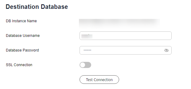
Table 9 DR database settings Parameter
Description
DB Instance Name
The TaurusDB instance you selected when creating the DR task. This parameter cannot be changed.
Database Username
The username for accessing the DR database.
Database Password
The password for the database username. The password can be changed after a task is created.
If the task is in the Starting, Initializing, Disaster recovery in progress, or Disaster recovery failed status, in the Connection Information area on the Basic Information tab, click Modify Connection Details. In the displayed dialog box, change the password.
The database username and password are encrypted and stored in DRS, and will be cleared after the task is deleted.
- On the Configure DR page, specify flow control and click Next. Figure 6 DR settings
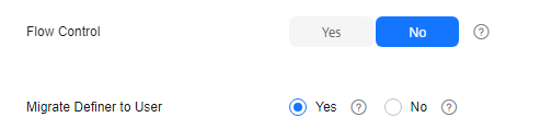
Table 10 DR settings Parameter
Description
Flow Control
You can choose whether to control the flow.
- Yes
You can customize the maximum disaster recovery speed. During the disaster recovery, the speed of each task (or each subtask in multi-task mode) does not exceed the value of this parameter.
In addition, you can set the time range based on your service requirements. The traffic rate setting usually includes setting of a rate limiting time period and a traffic rate value. Flow can be controlled all day or during specific time ranges. The default value is Always. A maximum of 10 time ranges can be set, and they cannot overlap.
The flow rate must be set based on the service scenario and cannot exceed 9,999 MB/s.
Figure 7 Flow control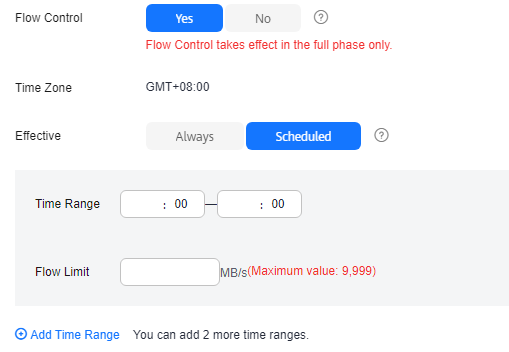
- No The DR speed is not limited and the outbound bandwidth of the source database is maximally used, which causes read consumption on the source database accordingly. For example, if the outbound bandwidth of the source database is 100 MB/s and 80% bandwidth is used, the I/O consumption on the source database is 80 MB/s.NOTE:
- Flow control mode takes effect only in the DR initialization phase.
- You can also change the flow control mode when the task is in the Configuration state. For details, see Modifying the Flow Control Mode.
Migrate Definer to User
Indicates whether to migrate the Definers of all source database objects to the destination database user entered during the connection test.
- Yes
The Definers of all source database objects will be migrated to the user. Other users do not have permissions for database objects unless these users are authorized. For details about authorization, see How Do I Maintain the Original Service User Permission System After Definer Is Forcibly Converted During MySQL Migration?
For example, if the view is CREATE ALGORITHM=UNDEFINED DEFINER=`username`@`%` SQL SECURITY DEFINER VIEW `test_db`.`view5` AS select 1 AS `1` before migration,
it is converted to CREATE ALGORITHM=UNDEFINED DEFINER=`drsUser`@`%` SQL SECURITY DEFINER VIEW `test_db`.`view5` AS select 1 AS `1` after the migration.
drsUser indicates the destination database user used for testing the connection.
- No
The Definers of all source database objects will not be changed. You need to migrate all accounts and permissions of the source database in the next step. Note that if the Definer account is not found in the destination database, unavailable objects will be created.
For details about Definer, see the MySQL official document.
- Yes
- On the Check Task page, check the DR task.
- If any check fails, review the failure cause and rectify the fault. After the fault is rectified, click Check Again.
For details about how to handle check failures, see Solutions to Failed Check Items in Data Replication Service User Guide.
- If the check is complete and the check success rate is 100%, click Next.
You can proceed to the next step only when all checks are successful. If there are any items that require confirmation, view and confirm the details first before proceeding to the next step.
- If any check fails, review the failure cause and rectify the fault. After the fault is rectified, click Check Again.
- On the Confirm Task page, specify Start Time, Send Notifications, SMN Topic, Delay Threshold, RPO Delay Threshold, RTO Delay Threshold, and Stop Abnormal Tasks After for the forward subtask. After confirming that the configured information is correct, click Submit to submit the forward DR task. Figure 8 Task startup settings
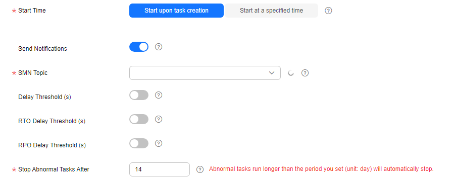
Table 11 Task settings Parameter
Description
Start Time
Set Start Time to Start upon task creation or Start at a specified time based on site requirements.
NOTE:After a DR task is started, the performance of the service and DR databases may be affected. You are advised to start a DR task during off-peak hours.
Send Notifications
SMN topic. This parameter is optional. If the status or latency metric of the DR task is abnormal, DRS will send a notification.
SMN Topic
This parameter is available only after you enable Send Notifications and create a topic on the SMN console and add a subscriber.
For details, see Simple Message Notification User Guide.
Delay Threshold (s)
During disaster recovery, a synchronization delay indicates a time difference (in seconds) of synchronization between the service and DR databases.
If the synchronization delay exceeds the threshold you specify, DRS will send alarms to the specified recipients. The value ranges from 0 to 3,600. To avoid repeated alarms caused by the fluctuation of delay, an alarm is sent only after the delay has exceeded the threshold for six minutes.
NOTE:- Before setting the delay threshold, enable Send Notifications.
- If the delay threshold is set to 0, no notifications will be sent to the recipient.
RTO Delay Threshold (s)
If the synchronization delay from the DRS instance to the DR database exceeds the threshold you specify, DRS will notify specified recipients. The value ranges from 0 to 3,600. To avoid repeated alarms caused by the fluctuation of delay, an alarm is sent only after the delay has exceeded the threshold for six minutes.
NOTE:- Before setting the RTO delay threshold, enable Send Notifications.
- If the delay threshold is set to 0, no notifications will be sent to the recipient.
RPO Delay Threshold (s)
If the synchronization delay from the DRS instance to the service database exceeds the threshold you specify, DRS will notify specified recipients. The value ranges from 0 to 3,600. To avoid repeated alarms caused by the fluctuation of delay, an alarm is sent only after the delay has exceeded the threshold for six minutes.
NOTE:- Before setting the delay threshold, enable Send Notifications.
- If the delay threshold is set to 0, no notifications will be sent to the recipient.
- In the early stages of an incremental DR, more delay is normal because more data is waiting to be synchronized. In this situation, no notifications will be sent.
Stop Abnormal Tasks After
Number of days after which an abnormal task automatically stops. The value must range from 14 to 100. The default value is 14.
NOTE:- You can set this parameter only for pay-per-use tasks.
- Tasks in the abnormal state are still charged. If tasks remain in the abnormal state for a long time, they cannot be resumed. Any task in the abnormal state that has run for longer than the period you set here (in days) will automatically stop to avoid unnecessary fees.
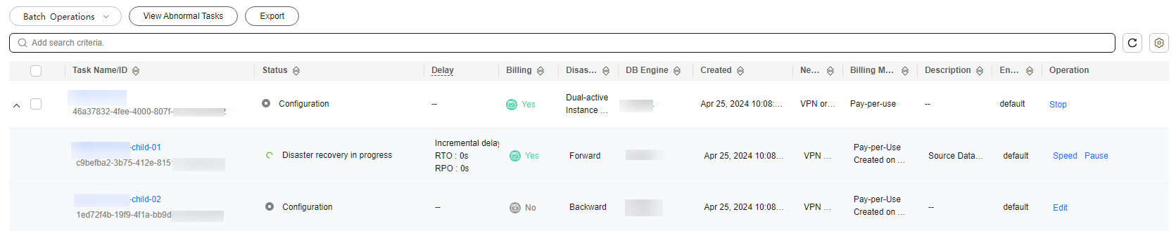
- Return to the Disaster Recovery Management page. After the forward subtask enters the Disaster recovery in progress state, locate the backward subtask and click Edit in the Operation column. The Configure Source and Destination Databases page of the backward subtask is displayed. Figure 9 DR task list
- On the Configure Source and Destination Databases page, click Test Connection for both the source and destination databases to check whether they have been connected to the disaster recovery instance. After the connection tests are successful, click Next.
- On the Confirm Task page, specify Start Time, Send Notifications, SMN Topic, Delay Threshold, RPO Delay Threshold, RTO Delay Threshold, and Stop Abnormal Tasks After for the backward subtask. After confirming that the configured information is correct, click Submit to submit the backward DR task.
- After the task is submitted, view and manage it on the Disaster Recovery Management page.
- You can view the task status. For more information about task status, see Task Statuses.
- You can click
 in the upper-right corner to view the latest task status.
 - By default, DRS retains a task in the Configuration state for three days. After three days, DRS automatically deletes background resources, but the task status remains unchanged. When you reconfigure the task, DRS applies for resources again.
- For a public network task, DRS needs to delete background resources after you stop the task. The EIP bound to the task cannot be restored to the Unbound state until background resources are deleted.
- For a task that is in the Disaster recovery in progress state, you can use data comparison to check whether data is consistent before and after the disaster recovery.
Feedback
Was this page helpful?
Provide feedbackThank you very much for your feedback. We will continue working to improve the documentation.


