To use enterprise routers and a Cloud Connect central network to allow on-premises networks from different regions to communicate with each other, you need to:
- Network Planning: Plan the required Direct Connect global DC gateways, virtual interfaces, and enterprise router route tables.
- Resource Planning: Plan the quantity, names, and other parameters of the Cloud Connect central network, Direct Connect resources, and enterprise routers.
Network Planning
Figure 1 shows the network planning for communications between on-premises networks across regions. Each on-premises data center is connected to an enterprise router through Direct Connect, and then the enterprise routers are connected to a Cloud Connect central network. Table 2 describes the details.
Figure 1 Communications between multiple on-premises data centers from different regions 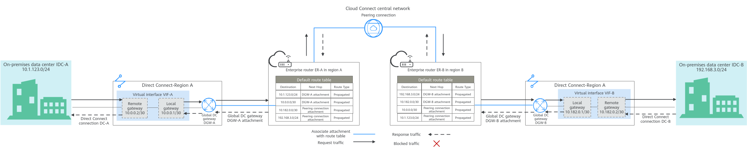
Table 1 Network traffic flows (Communications between multiple on-premises data centers across regions) | Path | Description |
| Request traffic: from IDC A, ER-A, ER-B, to IDC B | - In the route table of ER-A, there is route with peering connection attachment as the next hop and 192.168.3.0/24 as the destination to route traffic to ER-B through a Cloud Connect central network.
- In the route table of ER-B, there are two routes with DGW-B attachment as the next hop to forward traffic to global DC gateway DGW-B.
The destination of one route is 192.168.3.0/24, which is the CIDR block of IDC-B. The destination of the other route is 10.182.0.0/30, which is the gateway address of virtual interface VIF-B. - Virtual interface VIF-B is connected to global DC gateway DGW-B to forward traffic from the remote gateway to the Direct Connect connection DC-B.
- The traffic is then sent to IDC-B through Direct Connect connection DC-B.
|
| Response traffic: from IDC-B, ER-B, ER-A, to IDC-A | - In the route table of ER-B, there is route with peering connection attachment as the next hop and 10.1.123.0/24 as the destination to route traffic to ER-A through a Cloud Connect central network.
- In the route table of ER-A, there are two routes with DGW-A attachment as the next hop to forward traffic to global DC gateway DGW-A.
The destination of one route is 10.1.123.0/24, which is the CIDR block of IDC-A. The destination of the other route is 10.0.0.0/30, which is the gateway address of virtual interface VIF-A. - Virtual interface VIF-A is connected to global DC gateway DGW-A to forward traffic from the remote gateway to the Direct Connect connection DC-A.
- The traffic is then sent to IDC-A through Direct Connect connection DC-A.
|
Table 2 Network planning description for communications between multiple on-premises data centers across regions | Resource | Quantity | Description |
| Enterprise router | 2 | The network configuration for the enterprise routers in region A and region B is the same. Table 3 lists all routes required by the enterprise routers. When a central network is set up to connect the enterprise routers, you must enable Default Route Table Association and Default Route Table Propagation for the enterprise routers. In this way, when you create an attachment to such an enterprise router, a route pointing to the attachment will be automatically added for the enterprise router. |
| Direct Connect | 2 | The required resources in region A and region B are as follows: - There are two connections. Each links an on-premises data center to the cloud. In this example, there are connections DC-A in region A and DC-B in region B.
- There are two global DC gateways. Each is attached to an enterprise router. In this example, global DC gateway DGW-A in region A is attached to enterprise router ER-A, and DGW-B in region B is attached to ER-B.
- There are two virtual interfaces. Each connects a global DC gateway to a connection. In this example, there are virtual interfaces VIF-A in region A and VIF-B in region B.
|
| Central network | 1 | - Enterprise routers in different regions are added to the central network as attachments.
- A global connection bandwidth is required for assigning cross-site connection bandwidths to communicate across regions.
|
Table 3 Enterprise router route tables | Enterprise Router | Destination | Next Hop | Route Type |
| ER-A in region A | CIDR block of IDC-A: 10.1.123.0/24 | DGW-A attachment: er-attach-dgw-A | Propagated |
| Gateway of virtual interface VIF-A: 10.0.0.0/30 | DGW-A attachment: er-attach-dgw-A | Propagated |
| Gateway of virtual interface VIF-B: 10.182.0.0/30 | Peering connection attachment: region-A-region-B | Propagated |
| CIDR block of IDC-B: 192.168.3.0/24 | Peering connection attachment: region-A-region-B | Propagated |
| ER-B in region B | CIDR block of IDC-B: 192.168.3.0/24 | DGW-B attachment: er-attach-dgw-B | Propagated |
| Gateway of virtual interface VIF-B: 10.182.0.0/30 | DGW-B attachment: er-attach-dgw-B | Propagated |
| Gateway of virtual interface VIF-A: 10.0.0.0/30 | Peering connection attachment: region-B-region-A | Propagated |
| CIDR block of IDC-A: 10.1.123.0/24 | Peering connection attachment: region-B-region-A | Propagated |
Resource Planning
An enterprise router and its Direct Connect connection must be in the same region but can be in different AZs.
The following resource details are only for your reference. You can modify them if needed.
Table 4 Resource planning for communications between multiple on-premises data centers across regions | Resource | Quantity | Description |
| Enterprise router | 2 | An enterprise router is required in each of the two regions. Each enterprise router has a global DC gateway attachment from the same region and a peering connection attachment that is created between the two enterprise routers. - Name: Set it based on site requirements. In this example, the names are as follows:
- Region A: ER-A
- Region B: ER-B
- ASN: Set different ASNs for the enterprise routers. In this example, the ASNs are as follows:
- Default Route Table Association: This function must be enabled if a central network is used to connect the two enterprise routers.
- Default Route Table Propagation: This function must be enabled if a central network is used to connect the two enterprise routers.
- Auto Accept Shared Attachments: Set it based on site requirements. In this example, this option is enabled.
- Attachment: Two attachments are created for each enterprise router. In this example, the attachments are as follows:
ER-A: - Peering connection attachment region-A-region-B: connects enterprise routers ER-A to ER-B.
- Global DC gateway attachment er-attach-dgw-A: connects on-premises data center IDC-A and enterprise router ER-A.
ER-B: - Peering connection attachment region-B-region-A: connects enterprise routers ER-B to ER-A.
- Global DC gateway attachment er-attach-dgw-B: connects on-premises data center IDC-B and enterprise router ER-B.
|
| Direct Connect | 2 | Two connections are required. In this example, create connection DC-A in region A and DC-B in region B. |
Create two global DC gateways. - Name: Enter a name as required. In this example, the name of the global DC gateway in region A is DGW-A, and that in region B is DGW-B.
- BGP ASN: It is recommended that the ASN of a global DC gateway be different from that of its enterprise router. In this example, the ASN of the global DC gateway in region A is 64512, and that of the global DC gateway in region B is 64513.
- IP Address Family: Set this parameter based on site requirements. In this example, IPv4 is used.
|
Create two virtual interfaces. - Name: In this example, the name of the virtual interface in region A is VIF-A, and that in region B is VIF-B.
- Virtual Interface Priority: In this example, Preferred is selected.
- Connection: In this example, virtual interface VIF-A is associated with connection DC-A, and VIF-B is associated with DC-B.
- Global DC Gateway: In this example, virtual interface VIF-A is associated with global DC gateway DGW-A, and VIF-B associated with DGW-B.
- Local Gateway: In this example, the local gateway IP address range for virtual interface VIF-A is 10.0.0.1/30, and that for VIF-B is 10.182.0.1/30.
- Remote Gateway: In this example, the remote gateway IP address range for virtual interface VIF-A is 10.0.0.2/30, and that for VIF-B is 10.182.0.2/30.
- Remote Subnet: Specify the subnets of your on-premises data center. In this example, this value is set to 10.1.123.0/24 for virtual interface VIF-A and 192.168.3.0/24 for VIF-B.
- Routing Mode: In this example, BGP is selected.
- BGP ASN: ASN of the on-premises data center, which must be different from that used on the cloud (such as ASN of the global DC gateway or the enterprise router). In this example, the ASN of virtual interface VIF-A is 64855 and that of VIF-B is 64856.
|
| Attach global DC gateways to enterprise routers. - Resource Type: In this example, Peer link is selected.
- Peer Link Name: Enter a name as required. In this example, the link name of DGW-A is er-attach-dgw-A, and that of DGW-B is er-attach-dgw-B.
- Peer Link Type: In this example, Enterprise Router is selected.
- Link To: Select the enterprise router that the global DC gateway to be attached to. In this example, global DC gateway DGW-A is attached to enterprise router ER-A, and DGW-B is attached to ER-B.
|
| Cloud Connect central network | 1 | Create a central network, and add the two enterprise routers to it as attachments. - Name: Enter a name as required. In this example, the name is gcn-A-B.
- Policies:
- Region: Region A; Enterprise Router: ER-A
- Region: Region B; Enterprise Router: ER-B
- Cross-site connection bandwidth: Connects region A and region B. In this example, the bandwidth is 10 Mbit/s.
|
| Global connection bandwidth | 1 | One global connection bandwidth is required to connect the cloud backbone networks in different regions. - Bandwidth Name: Enter a name as required. In this example, the bandwidth name is bandwidth-A-B to connect networks in region A and region B.
- Bandwidth Type: Set it based on site requirements. In this example, Geographic-region is selected because region A and region B are in the same geographic region.
- Geographic Region: Set it based on site requirements. In this example, Chinese Mainland is selected because region A and region B are in Chinese Mainland.
- Connect Regions: Select the regions based on site requirements.
|


