

Configuring the Enterprise Router to Divert Traffic to CFW
Scenario
This section describes how to configure the enterprise router to divert traffic to CFW and verify network connectivity, so that the security of all traffic can be checked.
Prerequisites
Ensure normal communication when traffic between VPCs connected to the enterprise router bypasses the firewall. For details about traffic verification, see Verifying Network Connectivity.
Configuration Principle and Process
To let the enterprise router divert traffic to CFW, configure routing rules and traffic forwarding policies to make inter-VPC traffic pass through CFW for security check and filtering.
For example, VPC1 and VPC2 can communicate, and their traffic is forwarded to CFW through the enterprise router. CFW filters the traffic based on protection policies and lets the allowed traffic pass through the enterprise router. Then, the enterprise router forwards the traffic to VPC1 or VPC2. The traffic flow is as follows.
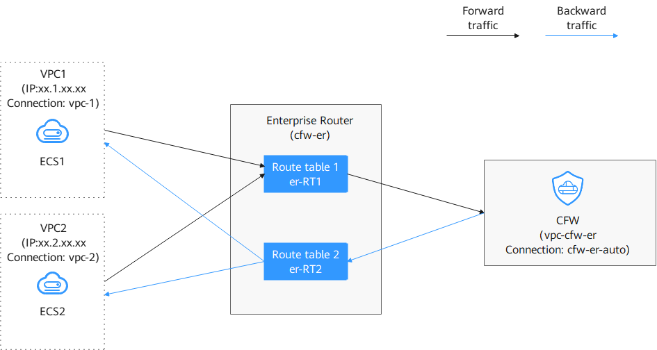
The process is as follows.
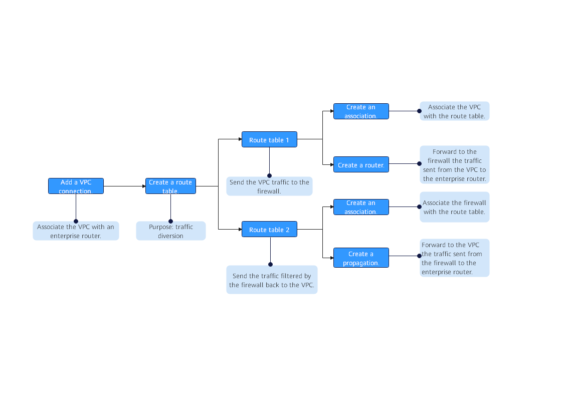
In this process, you need to create two dedicated route tables:
- Route table 1 (er-RT1, an association route table): Bind it to the attachments of VPC1 and VPC2. Configure route rules to direct VPC traffic to CFW. (The next hop is the cfw-er-auto-attach attachment automatically generated by CFW.) This ensures outbound VPC traffic can be protected.
- Route table 2 (er-RT2, a propagation route table): Bind it to the CFW attachment. It obtains VPC1 and VPC2 routes through propagation, so that CFW can send processed traffic to the correct VPC.
Notes and Constraints
In the VPC route table, when you configure the route with the enterprise router as the next hop, do not specify the default CIDR block 0.0.0.0/0. If an ECS in the VPC has an EIP bound, the VPC route table will have a policy-based route with the default CIDR block as the destination. This route has a higher priority than the route with the enterprise router as the next hop. In this case, traffic is forwarded to the EIP and cannot reach the enterprise router. Therefore, do not set the destination of a route (with an enterprise router as the next hop) to 0.0.0.0/0 in the VPC route table if the following conditions are met. Otherwise, some service traffic cannot be forwarded to the enterprise router.
- An ECS in the VPC has an EIP bound.
- The VPC has ELB, NAT Gateway, VPCEP, or DCS deployed.
For details about how to configure routes in the preceding scenario, see Why Traffic Can't Be Forwarded from a VPC with a Route Destination of 0.0.0.0/0 to Its Enterprise Router?
Diverting Traffic to the CFW
Select a configuration mode based on whether an enterprise router has been configured for the current service.
- A VPC border firewall has been created. For details, see Creating a VPC Border Firewall.
- (Optional) Switch to another firewall instance. If there are multiple firewall instances, you can select a desired instance from the drop-down list in the upper left corner of the page.
- In the navigation pane, choose Assets > Inter-VPC Border Firewalls.
- Add VPC attachments.
Click Edit Protected VPCs next to the firewall status. Add attachments on the enterprise router page that is displayed. For details about the supported attachment types, see Attachment Overview.
Assume you want to protect two VPCs. (At least two VPC attachments are required to connect the two VPCs to the enterprise router.) For details, see Adding VPC Attachments to an Enterprise Router.
Figure 3 Adding VPC attachments
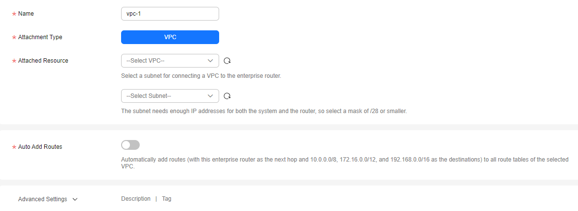
- After a firewall is created, a firewall attachment (named cfw-er-auto-attach and connected to the CFW instance) is automatically generated. You need to manually add an attachment for each protected VPC.
For example, the VPC1 attachment is named vpc-1, the VPC2 attachment is named vpc-2, and the VPC3 attachment is named vpc-3.
- To use the enterprise router of account A to protect VPCs under account B, share the router with account B. For details, see Creating a Sharing. After the sharing is successful, add attachments to account B. Subsequent configurations are still performed under account A.
- After a firewall is created, a firewall attachment (named cfw-er-auto-attach and connected to the CFW instance) is automatically generated. You need to manually add an attachment for each protected VPC.
- Create an association route table and a propagation route table, used for connecting to a protected VPC and a firewall, respectively.
On the enterprise router details page, click the Route Tables tab. On the route table configuration page, click Create Route Table. In the displayed dialog box, configure parameters.
Table 1 Route table parameters Parameter
Description
Example Value
Name
Route table name.
It must meet the following requirements:- Must contain 1 to 64 characters.
- Can contain letters, numbers, underscores (_), hyphens (-), and periods (.).
er-rtb-01
AS_Path Route Selection
(Optional)
- Do not configure: The system compares AS_Path attributes for the routes during load balancing and prefers the route with the shortest AS_Path length. The AS_Path attribute records all AS numbers that a BGP route passes through from the local end to the destination in the vector order. The fewer the AS numbers recorded in the AS_Path attribute, the shorter the AS_Path length.
- Ignore same length AS_Path: The system skips comparing the AS_Path attributes during load balancing if their lengths are identical. AS_Path prevents BGP loops between ASs. If you select this option, there may be BGP loops.
Do not configure
Tag
(Optional)
During the route table creation, you can tag the route table resources. Tags identify cloud resources for purposes of easy categorization and quick search.
For details about tags, see Tag Overview.
Tag key: test
Tag value: 01
Description
(Optional)
Route table description.
-
- Configure the association route table.
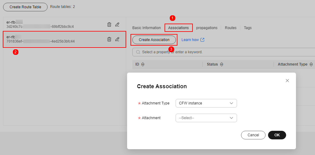
- Configure associations. On the route table configuration page, select the association table, click the Associations tab. On the displayed page, click Create Association. Set the parameters and click OK.
Create at least two associations. An association is required for each protected VPC you add.
For example, select attachment vpc-1 for VPC1 and vpc-2 for VPC2. To add VPC3 for protection, add an association and select attachment vpc-3.
Figure 4 Creating an association
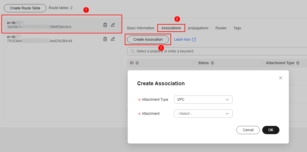
Table 2 Association parameters Parameter
Description
Attachment Type
Select VPC.
Attachment
Select an item from the Attachment drop-down list.
- Configure routes. Click the Routes tab and click Create Route. Configure the parameters and click OK. Create routes as needed. For details about the parameters, see Table 3. Figure 5 Creating a route
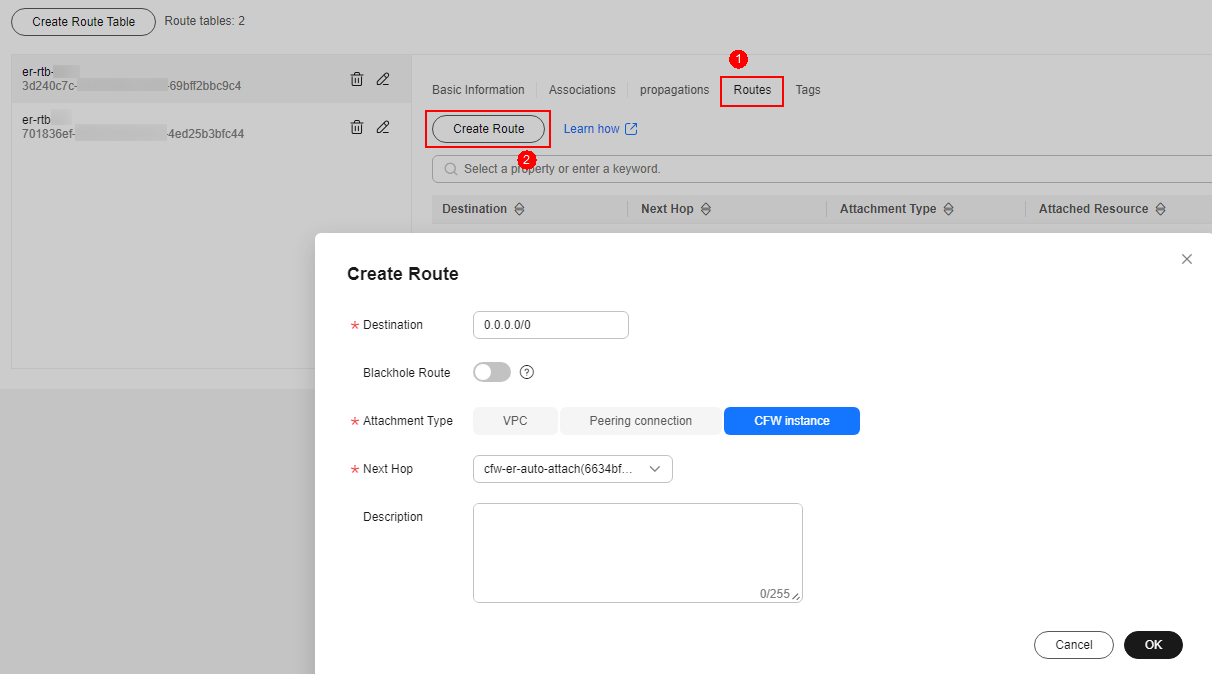
Table 3 Route parameters Parameter
Description
Destination
Set the destination address.
- If 0.0.0.0/0 is configured, all the traffic (IPv4) of the VPC is protected by CFW.
- If a CIDR block is configured, the traffic of the CIDR block is protected by CFW.
Blackhole Route
You are advised to disable this function. If it is enabled, the packets from a route that matches the destination address of the blackhole route will be discarded.
Attachment Type
Set Attachment Type to CFW instance.
Next Hop
Select the automatically generated firewall attachment cfw-er-auto-attach.
Description
(Optional) Description of a route.
- Configure associations. On the route table configuration page, select the association table, click the Associations tab. On the displayed page, click Create Association. Set the parameters and click OK.
- Configure the propagation route table.
- Configure associations. On the route table configuration page, select the propagation table, click the Associations tab, and click Create Association. For more information, see Table 4. Figure 6 Creating an association
- Set the propagation function. Click the Propagations tab and click Create Propagation. For more information, see Table 5. Figure 7 Creating a propagation
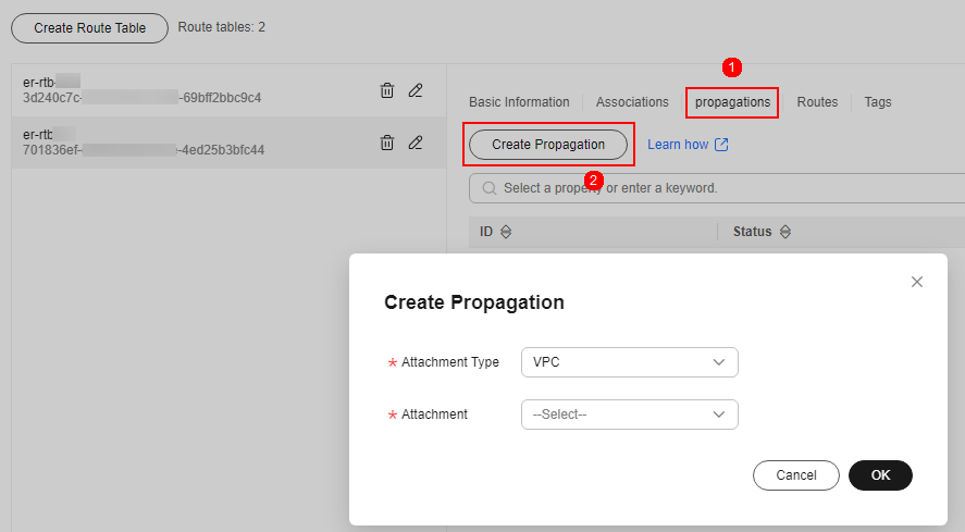
Table 5 Propagation parameters Parameter
Description
Attachment Type
Select VPC.
Attachment
Select an item from the Attachment drop-down list.
- Add at least two propagations. A propagation is required for each protected VPC you add.
For example, select attachment vpc-1 for VPC1 and vpc-2 for VPC2. To add VPC3 for protection, add a propagation and select attachment vpc-3.
- After a propagation is created, its route information will be extracted to the route table of the enterprise router, and a propagation route will be generated. In the same route table, the destinations of different propagation routes may be the same, and cannot be modified or deleted.
- You can add static routes for the attachments in a route table. The destinations of static routes in a table must be unique, and can be modified or deleted.
- If a static route and a propagation route in the same route table happen to use the same destination, the static route takes effect first.
- Add at least two propagations. A propagation is required for each protected VPC you add.
- Configure associations. On the route table configuration page, select the propagation table, click the Associations tab, and click Create Association. For more information, see Table 4.
- Modify the VPC route table.
- In the navigation pane, choose Network Console > Virtual Private Cloud > Route Tables.
- In the Name/ID column, click the route table name of a VPC. The Summary page is displayed.
- Click Add Route. In the displayed dialog box, configure the parameters.
You need to add routes for at least two VPCs. Each time a protected VPC is added, you need to add a route for that VPC.
Table 6 Route parameters Parameter
Description
Destination Address Type
Select IP address.
Destination
Enter the CIDR block that the traffic is sent to.
For example, for inter-VPC protection, enter the CIDR block of VPC 2 in the Destination of the route of VPC 1.
Next Hop Type
Select Enterprise Router from the drop-down list.
Next Hop
Select a resource for the next hop.
The enterprise routers you created are displayed in the drop-down list.
Description
(Optional) Description of a route.
Enter up to 255 characters. Angle brackets (< or >) are not allowed.
- Click OK.
- A VPC border firewall has been created. For details, see Creating a VPC Border Firewall.
- Log in to the Enterprise Router console.
- Click
 in the upper left corner of the management console and select a region.
 - Delete the associations and propagations of the firewall VPC (vpc-cfw-er) from the default route table er-RT1.
Click the route table and click the Associations tab. In the Operation column of the firewall VPC, click Delete. In the confirmation dialog box, click Yes.
Click the Propagations tab. In the Operation column of the firewall VPC, click Delete. In the confirmation dialog box, click Yes.
- Create route table er-RT2.
Click Create Route Table. For details, see Table 7.
Table 7 Route table parameters Parameter
Description
Example Value
Name
Route table name. The name:
- Must contain 1 to 64 characters.
- Can contain letters, numbers, underscores (_), hyphens (-), and periods (.).
er-RT2
Tags
During the route table creation, you can add tags to the route table resources for easy categorization and quick search.
For details about tags, see Tag Overview.
Tag key: test
Tag value: 01
Description
Route table description
-
- Configure the route table er-RT2. Set the associations and propagations.
- Select the route table er-RT2, click the Associations tab, and click Create Association. See Creating an association. For more information, see Table 8.
- Create propagations for the route table (er-RT2). Click the Propagations tab and click Create Propagation. For details, see Table 9. Figure 9 Creating a propagation
Table 9 Propagation parameters Parameter
Description
Example Value
Attachment Type
Select VPC.
VPC
Attachment
Select an item from the Attachment drop-down list.
vpc-1
Table 10 Propagation parameters Parameter
Description
Example Value
Attachment Type
Select VPC.
VPC
Attachment
Select an item from the Attachment drop-down list.
vpc-2
- Add at least two propagations. A propagation is required for each protected VPC you add.
For example, select attachment vpc-1 for VPC1 and vpc-2 for VPC2. To add VPC3 for protection, add a propagation and select attachment vpc-3.
- After a propagation is created, its route information will be extracted to the route table of the enterprise router, and a propagation route will be generated. In the same route table, the destinations of different propagation routes may be the same, and cannot be modified or deleted.
- You can add static routes for the attachments in a route table. The destinations of static routes in a table must be unique, and can be modified or deleted.
- If a static route and a propagation route in the same route table happen to use the same destination, the static route takes effect first.
- Add at least two propagations. A propagation is required for each protected VPC you add.
- Configure the default route table er-RT1.
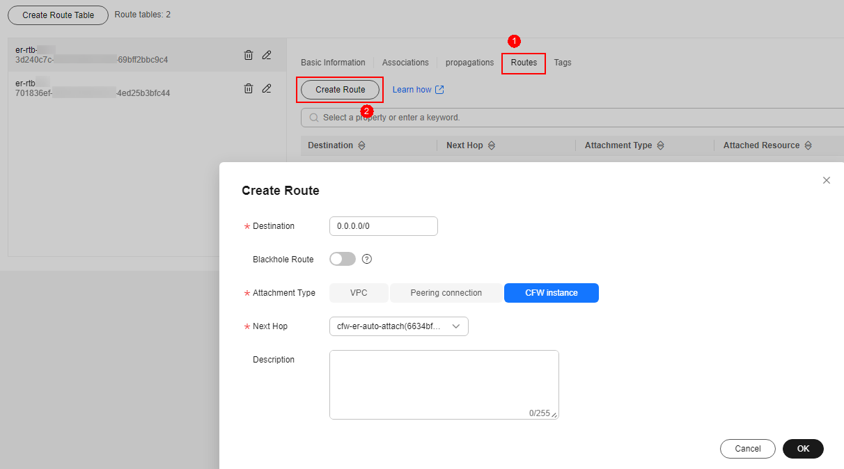
- Add a static route. Select the route table er-RT1, click the Routes tab, click Create Route, and configure the following parameters:
- Destination: 0.0.0.0/0
- Attachment Type: CFW instance
- Next Hop: cfw-er-auto (attachment of the firewall VPC)
Figure 10 Adding a static route
- Delete all the propagations in the route table er-RT1.
Click the Propagations tab. In the Operation column, click Delete. In the confirmation dialog box, click Yes.
- Add a static route. Select the route table er-RT1, click the Routes tab, click Create Route, and configure the following parameters:
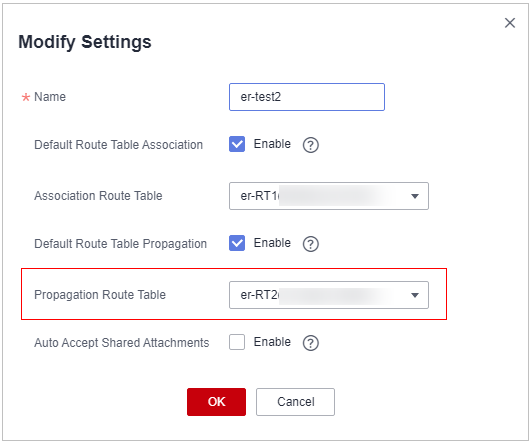
- (Optional) You are advised to change the propagation route table of the enterprise router to the new route table (er-RT2), so that you simply need to configure an attachment when adding a VPC. Go to the Enterprise Router page, choose More > Modify Settings, and set the propagation route table to er-RT2.Figure 11 Modifying configurations
To use the enterprise router of account A to protect VPCs under account B, share the router with account B, and add an attachment in account B. For details, see Creating a Sharing.
Follow-up Operations
After the configuration, enable VPC border protection. For details, see Enabling the VPC Border Firewall and Ensuring the Traffic Passes Through CFW.
What is your overall rating for this page?
Thank you very much for your feedback. We will continue working to improve the documentation.See the reply and handling status in My Cloud VOC.
For any further questions, feel free to contact us through the chatbot.
Chatbot


