
Creating a Blank Flow
Flows allow you to develop services through simple drag-and-drop and parameter configuration. This section describes the process of creating a flow to configure welcome messages based on the input username.
Video Tutorial
This video shows how to develop application logic using flows.
Creating a Flow
- Log in to the application designer by referring to Logging In to the Application Designer.
- In the navigation pane, choose Logic.
- (Optional) Click
 next to Flow to add a folder.
 By default, flows are stored in the root folder. Before creating a flow, you can create a folder for storing the flow. You can drag the flow to a specified folder.
- Click
 next to Flow. The page for adding a flow is displayed.
 Alternatively, click
 next to Flow to go to the page for adding a flow.
 - Complete the configuration and click Add. Figure 1 Creating a flow

- Create a variable.
- In the flow designer, click
 . The Context panel is displayed.
 - Click
 next to Variable to create variables by referring to Table 2. Figure 2 Creating variables
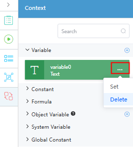
Table 2 Variables Name
Type
Description
userName
Text
Input username.
message
Text
Welcome information.
In Context, in addition to creating variables of basic types, as well as other variable types (such as Creating a Constant, Creating a Formula, Creating a Private Struct, and Creating Object Variables, Struct Variables, and Event Variables).
- In the flow designer, click
- Click
 and set input and output parameters for the flow. Figure 3 Setting input and output parameters
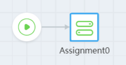
- Drag the Assignment diagram element from Logic to the canvas.
The Assignment diagram element can assign values to parameters such as variables in the context. For details about other diagram elements, see Configuring Diagram Elements for Flows.
Figure 4 Dragging the Assignment diagram element to the canvas
- Configure the diagram element.
- Select the Assignment diagram element and click
 .
. - On the Assignment panel, click Add Row and drag the created variable to the corresponding position, as shown in the following figure.
Assign the value of "Hello," to the message variable and concatenate the userName variable to the message variable. The assignment statement is executed from top to bottom.
Figure 5 Configuring the Assignment diagram element
- Select the Assignment diagram element and click
- Connect diagram elements to specify their logical relationship. For example, connecting the Start element to the Assignment element means the Assignment's statement executes once the flow begins. Figure 6 Connecting diagram elements
- Click
 in the upper part of the editor to save the settings.
 - Click
 . The flow debugging page is displayed.
 Enter the following information in the input parameter text box and click Run:
{
    "userName": "Flow"
}
The output is Hello,Flow, as shown in the following figure.
Figure 7 Output
- Click
 in the upper part of the editor to activate the flow.
 Only activated flows can be referenced by other functions such as scripts and business processes.
- Debug the created flow.
- In the navigation pane of the application designer, choose Integrations.
- Click + next to Open API, create a helloFlow open API, and click Save. Figure 8 Creating a helloFlow open API

- Move the cursor to
 of the created open API, click , and choose Check.
 - On the preview page, click
 .
. - Click Try it out, enter the sample model, and click the execution button to run the API. Figure 9 Testing the API

After the execution is successful, you can view the API test result.
{
    "resCode": "0",
    "resMsg": "Success",
    "result": [
        {
            "message": "Hello, Flow"
        }
    ]
}
Creating a Constant
In flows and interactions, values or parameters that remain unchanged are constants, such as service IDs, access addresses, and error codes.
- On the right of the flow designer, click
 .
. - On the Context panel, click
 next to Constant.
 - Click ... next to the new constant and choose Set.
- Complete the configuration and click Save. Figure 10 Configuring a constant

Table 3 Constant parameters Parameter
Description
Name
Constant name, which is the unique identifier for a constant in a flow. Changing this name does not change its reference in the diagram element, but causes the flow to be unavailable.
Data Type
Data type of the constant. Select a value from the drop-down list. The default value is Text.
Value
Constant value. The string constant must be enclosed in double quotation marks, for example, "abc".
Description
Description of the constant.
External Use
If this option is selected, the constant is used externally. During compilation, the system does not check whether the constant is used.
This option is deselected by default.
Creating a Formula
In flows, formulas are used to assign values to variables, perform calculations, and transfer parameters.
- On the right of the flow designer, click
 .
. - On the Context panel, click
 next to Formula.
 - Complete the configuration and click Save. Figure 11 Configuring a formula

Table 4 Formula parameters Parameter
Description
Name
Formula name.
Data Type
Data type of the formula. Select a value from the drop-down list. The default value is Text.
Description
Description of the formula.
External Use
If this option is selected, the formula is used externally. During compilation, the system does not check whether the formula is used.
This option is deselected by default.
Expression
Formula expression. If a formula needs to be used in an expression, you can double-click the required formula preconfigured in the function area. Then the formula is displayed in the expression area. If a variable parameter is required in an expression, you can drag the required variable from the variable area to the expression.
Creating a Private Struct
For flows with complex struct parameters, create either a global or private struct and use it as a parameter type. To define these struct variables for the flow's parameters, see Creating Object Variables, Struct Variables, and Event Variables.
- On the right of the flow designer, click
 and click Add on the Private Structure panel. There are two Add buttons. The Add button in the upper part is used to create a private struct by setting parameters on the page. The Add button in the lower part is used to define a private struct by entering the data source code of the JSON Schema type.Figure 12 Adding a private struct
- (Perform this step if you click Add in the upper part of the Private Structure panel.) Set parameters on the page.
- In the basic information area, enter the struct name and description.
- In the Struct Members area, set member variables, including the name, description, data type, whether the variable is mandatory, and whether the variable is a collection variable. Click Add to add member variables. You can set member variables of the global struct or private struct. If the member variables of a private struct contain the struct type, you need to define the member struct in advance. For example, in the following figure, the member variable hobby is a private struct. You need to create a private struct create in advance.
Figure 13 Configuring a private structure
- (Perform this step if you click second Add in the lower part of the Private Structure panel in the previous step.) On the Create JSON Schema page, enter a name. In the JSON Source Code area, enter the data source code and click
 . The system performs validation and converts the code into the struct types in the flow. Then, click Save. Figure 14 Creating JSON Schema
The following is an example of the data source code:
{
    "name": "xiaoming",
    "age": 18,
    "father": {
        "name": "daliu",
        "gender": "male"
    },
    "brother": {
        "name": "xiaolei",
        "gender": "male"
    }
}
After the creation is successful, the following page is displayed.
Figure 15 Private structure created
If the structure created in this mode contains member structs, the definitions of the member structs are not displayed on the GUI and other structs cannot be referenced.
The JSON struct supports nesting. For example, in the JSON Schema Struct area, click Add to add the company struct. In the company struct, ceo references the family struct, as shown in the following figure. You can use the dollar sign ($) to select another struct in the current flow for nested reference.
Figure 16 Referencing other structs
Creating Object Variables, Struct Variables, and Event Variables
Object variables are used to reference or operate specific object instances in a flow. They are used in simple service processes. Struct variables allow multiple data items of different types to be combined. They are usually used in complex service processes. Event variables indicate events that occur in the system or service process. Events can originate internally or be externally triggered.
- On the right of the flow designer, click
 .
. - On the Context panel, click
 next to Object Variable.
 - Complete the configuration. The following describes how to create an object variable. Figure 17 Configuring an object variable

Table 5 Parameters for creating an object variable Parameter
Description
Name
Name of the new object variable. The name is the unique identifier of the variable referenced in a flow. Changing this name does not change its reference in the diagram element, but causes the flow to be unavailable.
Object
Select an object from the drop-down list. This parameter is displayed only when Object is selected.
Global
Select a global struct from the drop-down list. This parameter is displayed only when Global is selected.
Private
Select a private struct from the drop-down list. This parameter is displayed only when Private is selected.
Event
Select an event from the drop-down list. If Event is selected, member variables are customized fields of the event, excluding preset standard fields. This parameter is displayed only when Event is selected.
Default Value
Enter the default value of the variable or select a value from the drop-down list.
Description
Description of the variable.
Value: 1–255 characters.
Is Collection
Whether the variable is an array variable, that is, a collection variable.
This parameter is deselected by default.
External Use
If this option is selected, the formula is used externally. During compilation, the system does not check whether the formula is used.
This parameter is deselected by default.
Feedback
Was this page helpful?
Provide feedbackThank you very much for your feedback. We will continue working to improve the documentation.See the reply and handling status in My Cloud VOC.
For any further questions, feel free to contact us through the chatbot.
Chatbot


