Development Guide
Overview
If a device reports binary data, a codec must be developed for data format conversion. If a device reports JSON data, codec development is not required.
For example, in the NB-IoT scenario where devices communicate with the IoT platform using CoAP, the payload of the CoAP message is data at the application layer and the data type is defined by the device. As NB-IoT devices require low power consumption, data at the application layer is in binary format instead of JSON. However, the IoT platform communicates with NAs by sending data in JSON format. Therefore, codec development is required for the IoT platform to convert data in binary and JSON formats.

Procedure
If you have used a preset template when creating a project and product, you can directly use or modify the codecs contained in the template. If a customized product is created, you must develop your codec.
- In the product development space, click Codec Development.

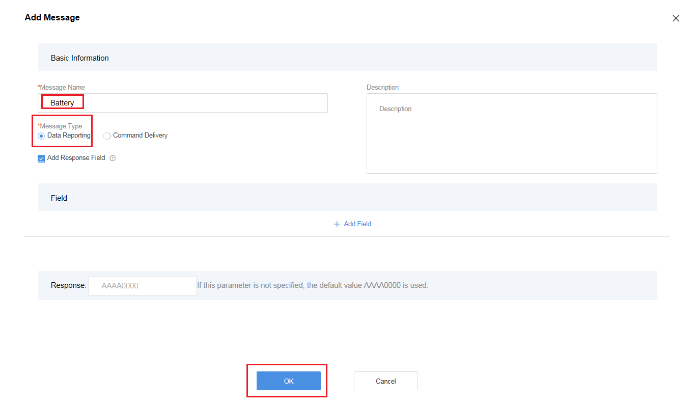
- In the Online Codec Editor area, click Add Message.

- In the Add Message dialog box, specify Message Name, set Message Type to Data Reporting, and click OK.
- If the IoT platform is required to return an ACK message after receiving data reported by the device, select Add Response Field. The data carried in the ACK message is the value of Response. The default value is AAAA0000.
- Message Name can contain only letters, digits, underscores (_), and dollar signs ($) and cannot start with a digit.
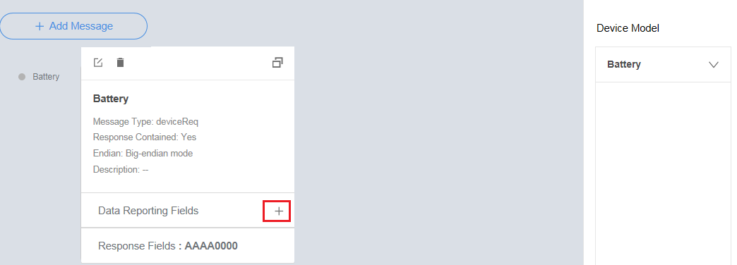
- Click + next to Data Reporting Fields.
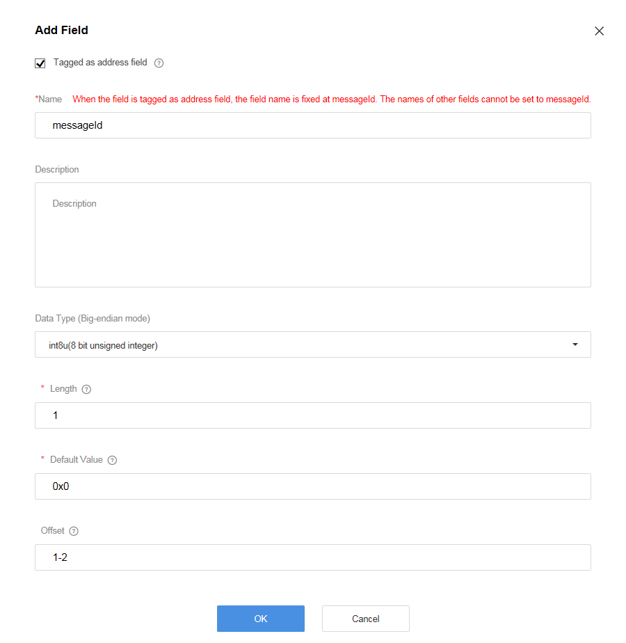
- In the Add Field dialog box, select Tagged as address field. Other parameters are set automatically. Click OK.
When messages of the same type are created, such as two data reporting messages, Tagged as address field must be selected and this field in every such message must be in the same place on the field list. A command response can be regarded as a type of data reporting message. Therefore, if a command response exists, messageId must be added to the data reporting message.
- Click + next to Data Reporting Fields.

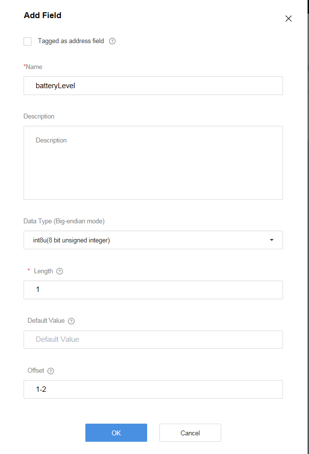
- In the Add Field dialog box, set the parameters and click OK.
- Name can contain only letters, digits, underscores (_), and dollar signs ($) and cannot start with a digit.
- Data Type is configured based on the data reported by the device and must match the type defined in the profile file.
- In the Online Codec Editor area, click Add Message.
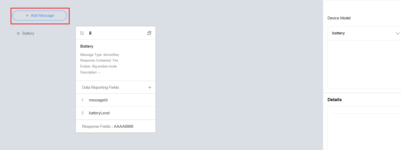
- In the Add Message dialog box, specify Message Name, set Message Type to Command Delivery, and click OK.
- If the device is required to return the command execution result, select Add Response Field. After the check box is selected:
- The address field must be defined in both the data reporting message and the command response, and this field in the two messages must be in the same place on the field list, so that the codec can distinguish the data reporting message from the command response.
- The response ID field must be defined in the command delivery message and the command response, and this field in the two messages must be in the same place on the field list, so that the codec can associate the command delivery message with the corresponding command response.
- Message Name can contain only letters, digits, underscores (_), and dollar signs ($) and cannot start with a digit.

- If the device is required to return the command execution result, select Add Response Field. After the check box is selected:
- Click + next to Command Delivery Fields.
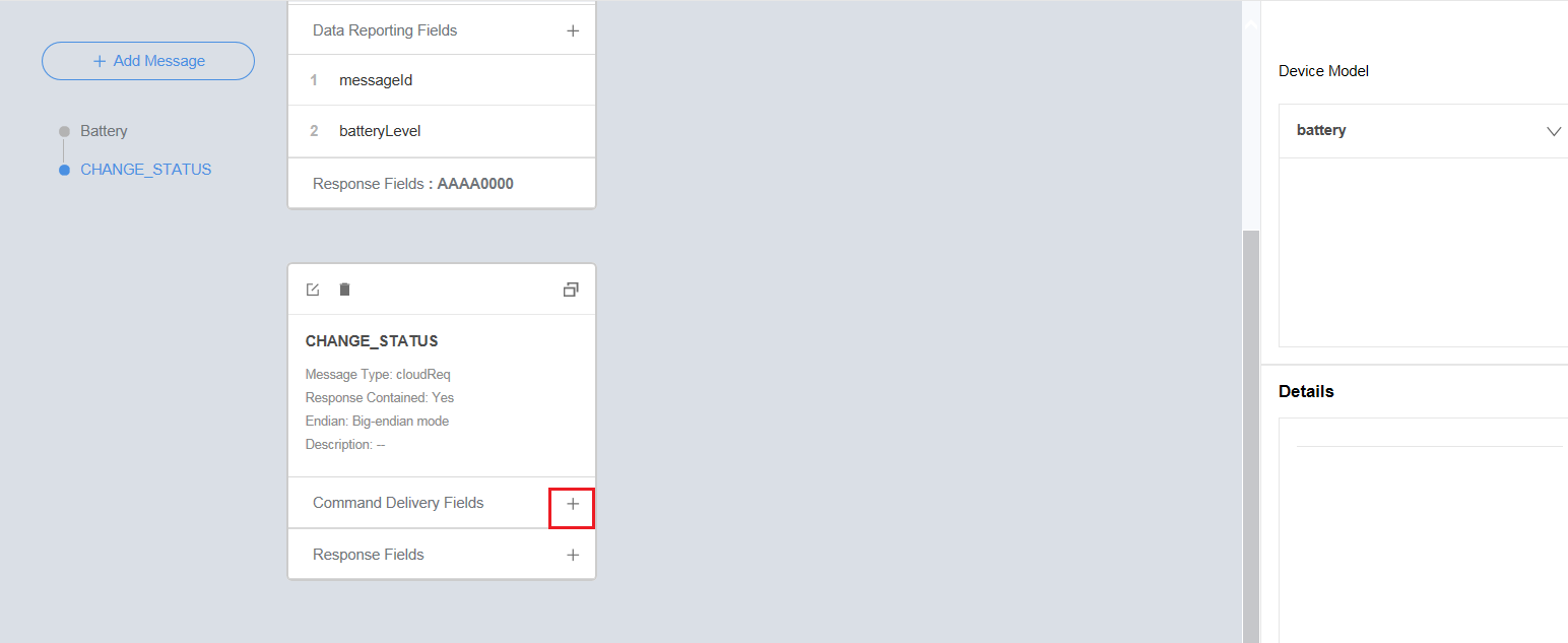
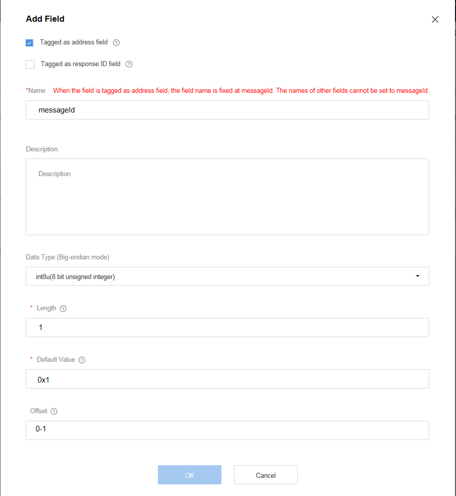
- In the Add Field dialog box, select Tagged as address field. Other parameters are set automatically. Click OK.
When messages of the same type are created, such as two command delivery messages, Tagged as address field must be selected and this field in every such message must be in the same place on the field list. A data reporting response can be regarded as a type of command delivery message. Therefore, if a data reporting response exists, messageId must be added to the command delivery message.
- Click + next to Command Delivery Fields.
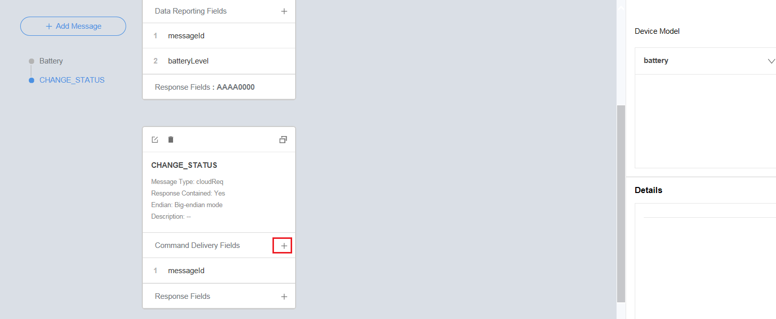
- In the Add Field dialog box, select Tagged as response ID field. Other parameters are set automatically. Click OK.
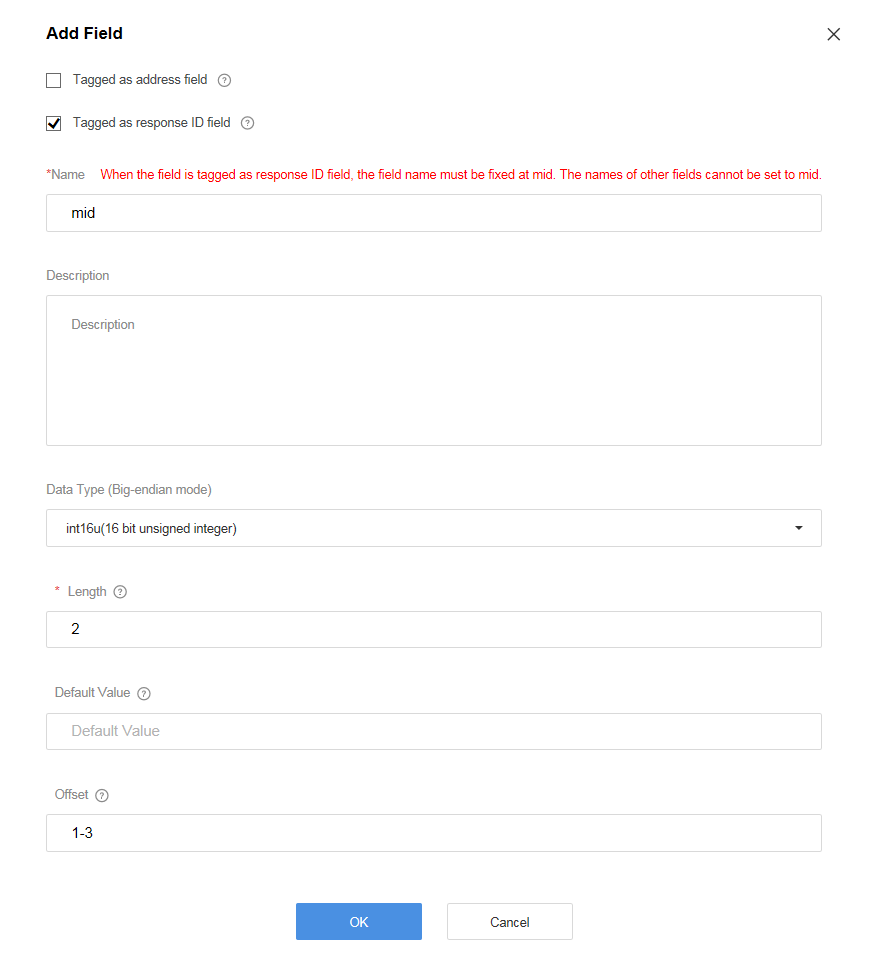
- Click + next to Command Delivery Fields.
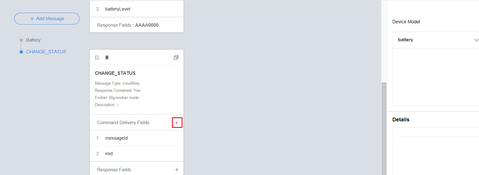
- In the Add Field dialog box, set the parameters and click OK.
- Name can contain only letters, digits, underscores (_), and dollar signs ($) and cannot start with a digit.
- Data Type is configured based on the data reported by the device and must match the type defined in the profile file.
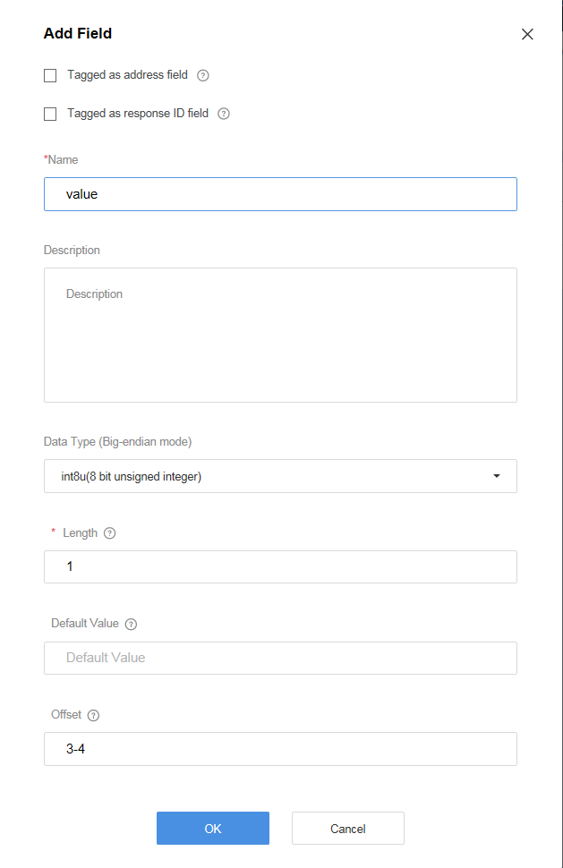
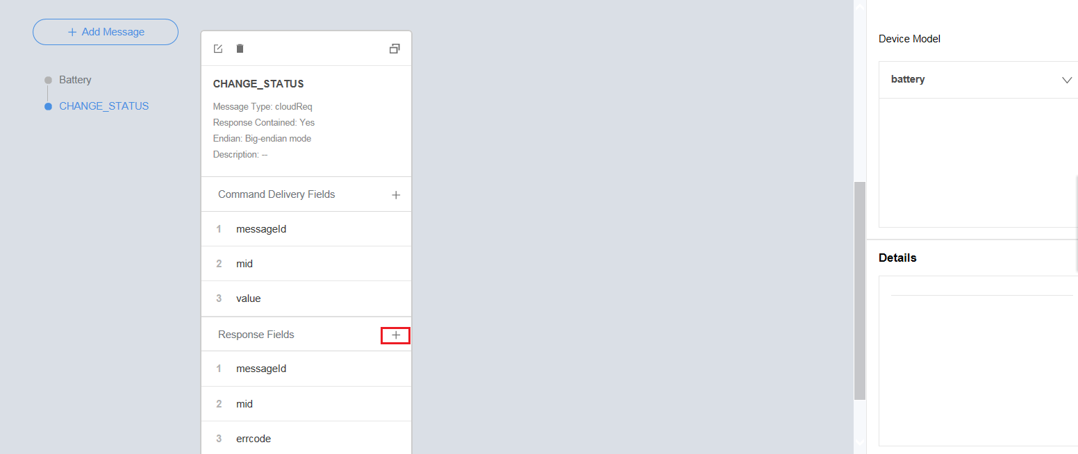
- Click + next to Response Fields.
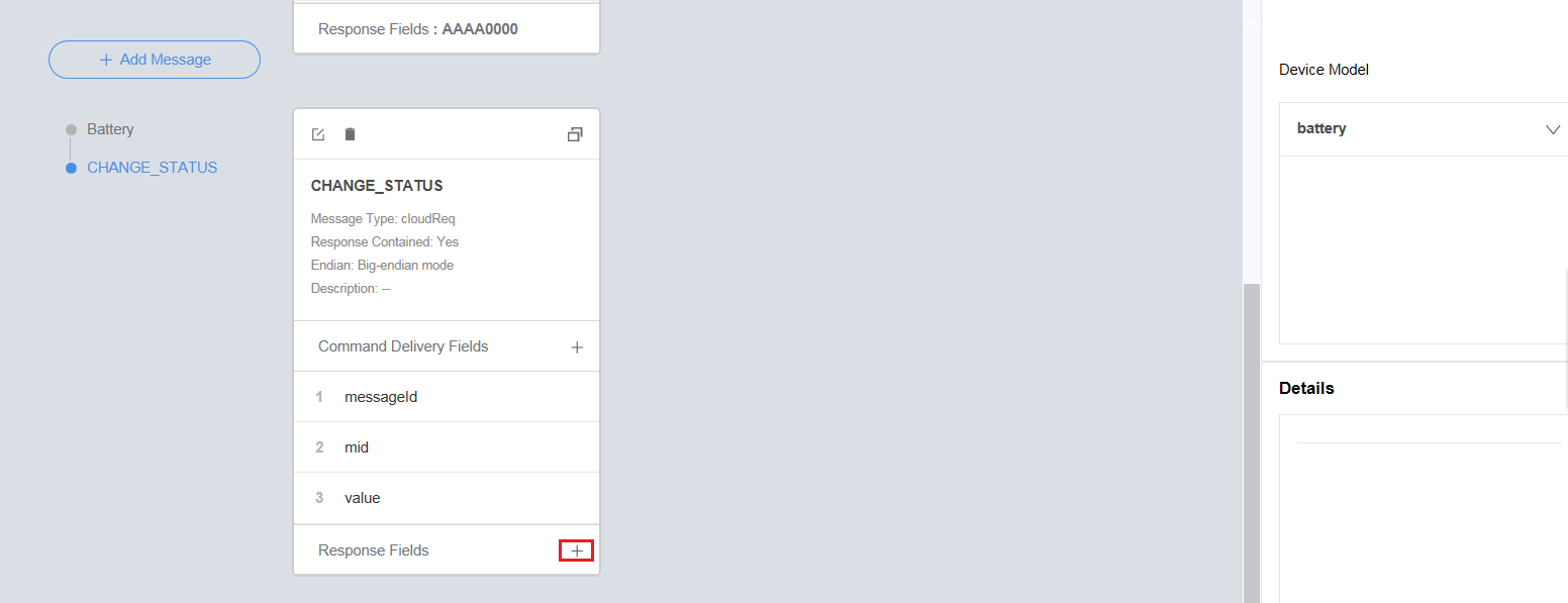
- In the Add Field dialog box, select Tagged as address field. Other parameters are set automatically. Click OK.
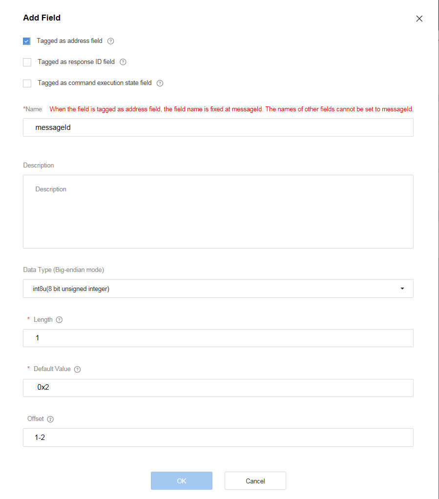
- Click + next to Response Fields.
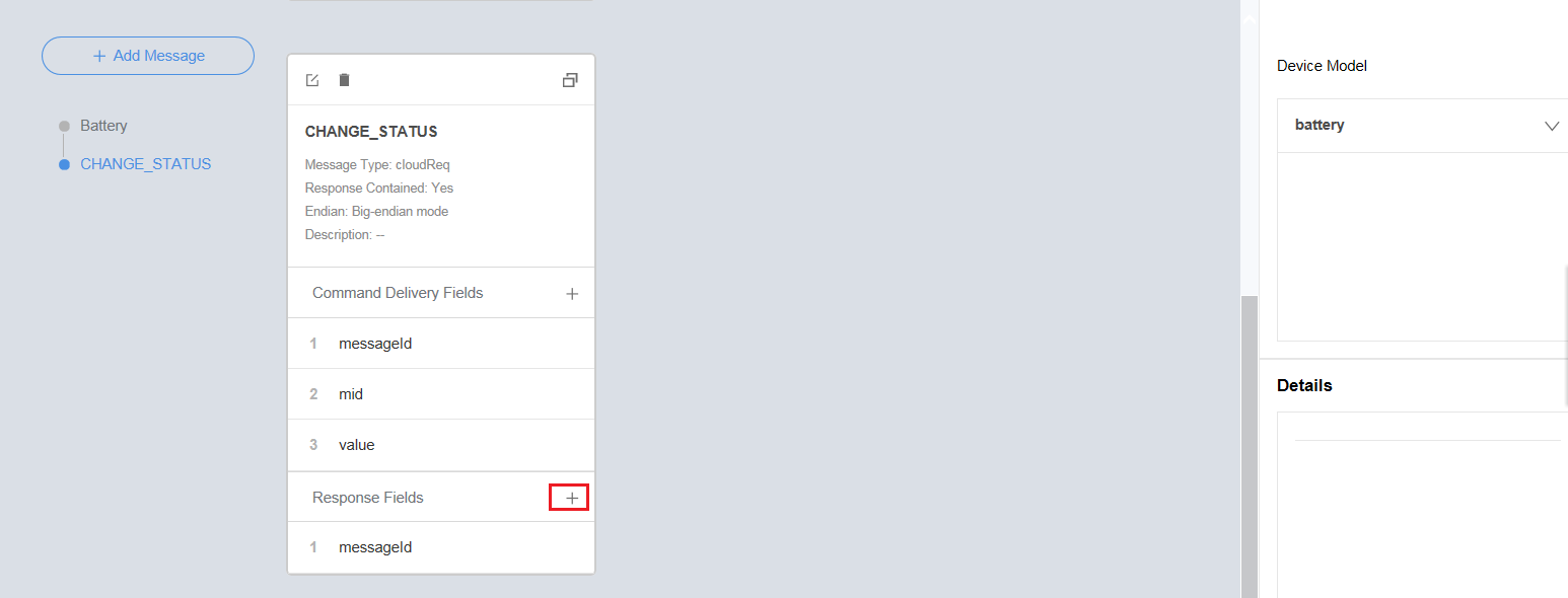
- In the Add Field dialog box, select Tagged as response ID field. Other parameters are set automatically. Click OK.
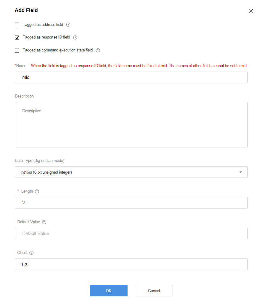
- Click + next to Response Fields.
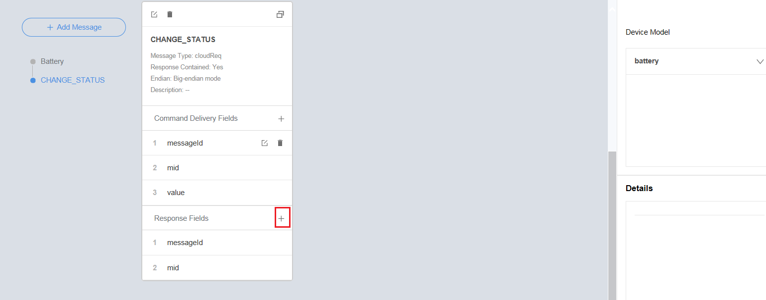
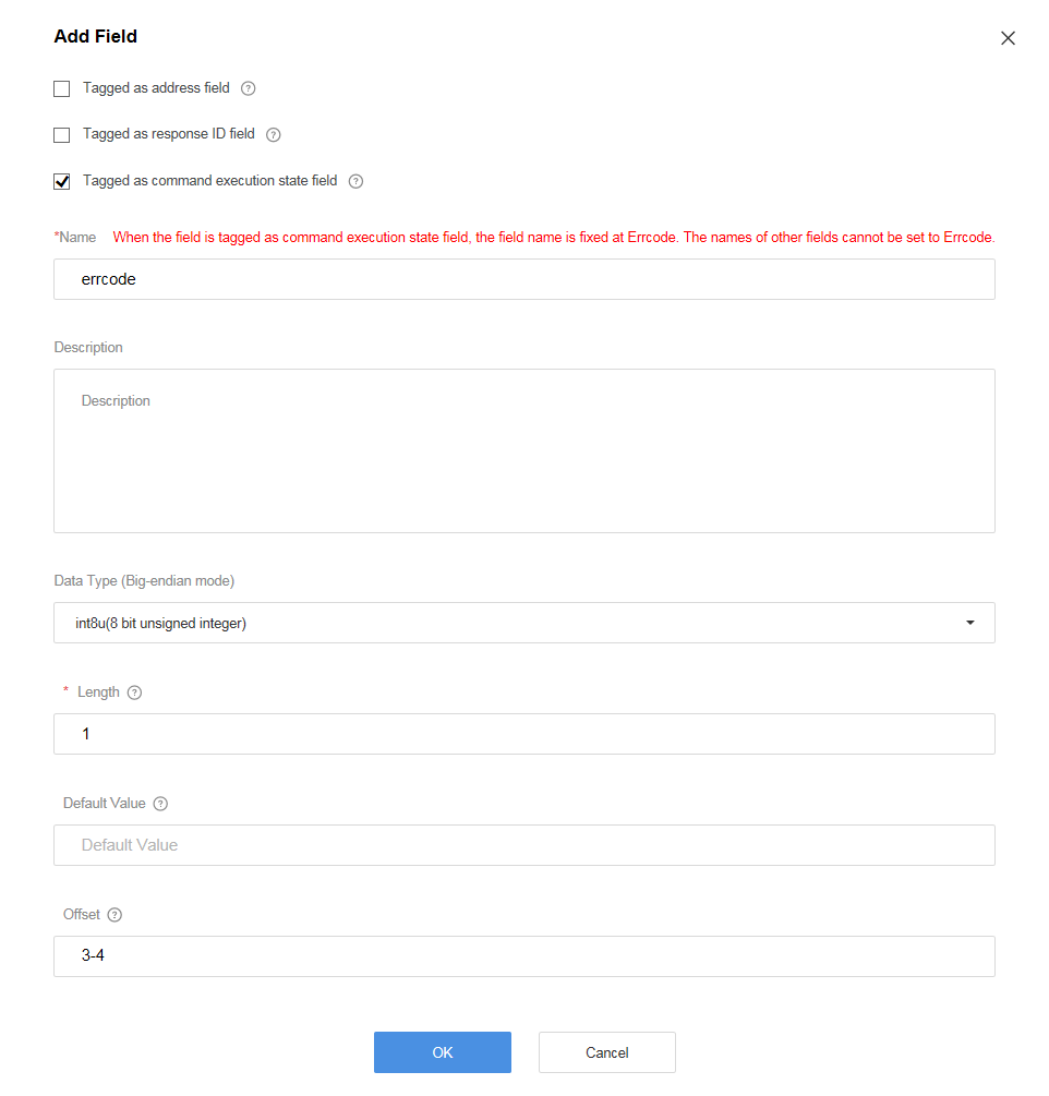
- In the Add Field dialog box, select Tagged as command execution state field, set the other parameters, and click OK.
- The value of Name is automatically populated.
- Data Type is configured based on the actual command response and must match the type of the corresponding field defined in the profile file.
- Click + next to Response Fields.
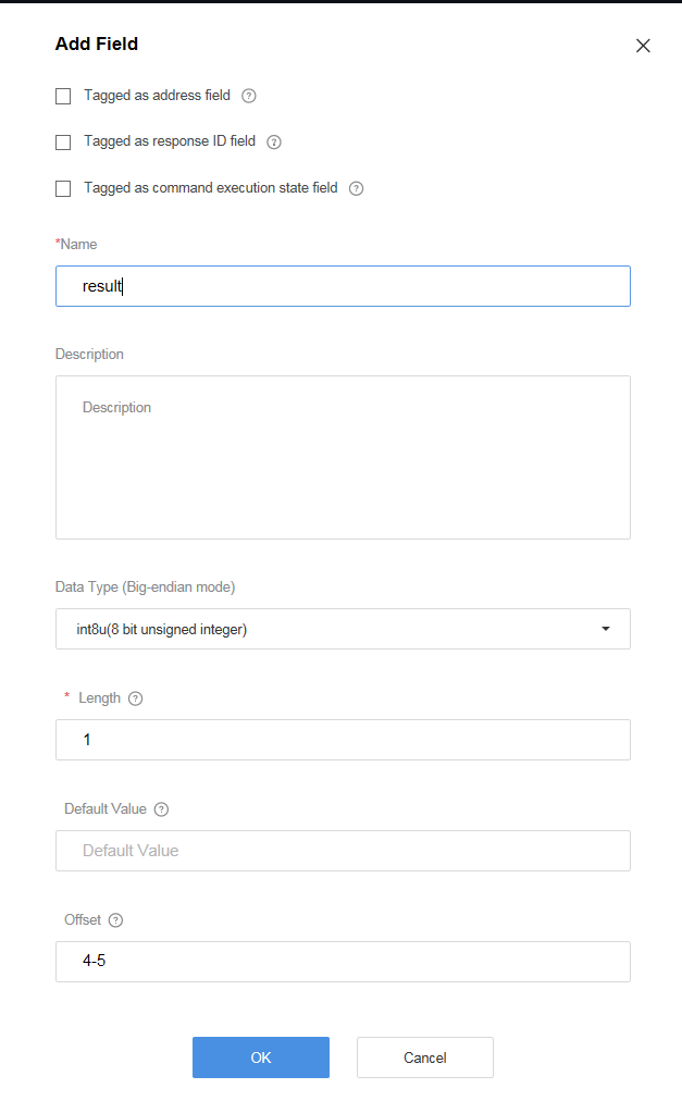
- In the Add Field dialog box, set the parameters and click OK.
- Name can contain only letters, digits, underscores (_), and dollar signs ($) and cannot start with a digit.
- Data Type is configured based on the data reported by the device and must match the type defined in the profile file.
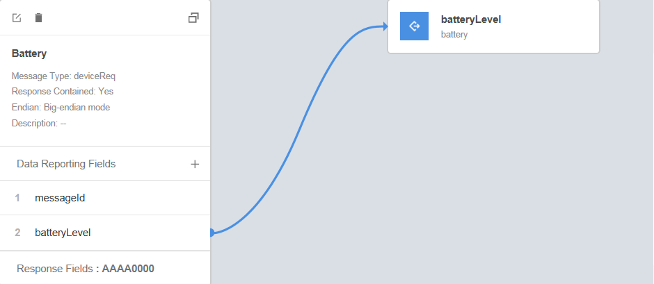
- Map the property fields, command fields, and response fields in Device Model on the right with the fields in the data reporting message, command delivery message, and command response.
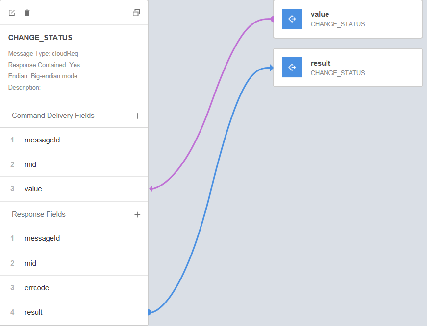
- Click Save and then Deploy to deploy the codec on the IoT platform.

Feedback
Was this page helpful?
Provide feedbackThank you very much for your feedback. We will continue working to improve the documentation.See the reply and handling status in My Cloud VOC.
For any further questions, feel free to contact us through the chatbot.
Chatbot


