Connecting and Debugging an NB-IoT Smart Street Light Using a Simulator
Scenarios
This section uses a smart street light as an example to describe how to use the device and application simulators provided by the IoTDA console to experience data reporting and command delivery.
Assume that:
A street light reports a data message carrying the light intensity (light_intensity) and status (light_status). The data message is in binary format. The command (SWITCH_LIGHT) can be used to remotely control the street light status.
Prerequisites
- You have registered a Huawei Cloud account.
- You have subscribed to IoTDA. If you have not subscribed to the service, go to the IoTDA service page, and click Access Console to subscribe to the service.
(Optional) Creating a Resource Space
A resource space is the commissioning space provided by the platform for applications and devices. You can create different resource spaces for different scenarios.
The system provides a preset resource space, where you can develop product models and codecs for devices online. To create a resource space, perform the following steps:
- Visit the IoTDA service page and click Access Console.
- In the navigation pane, choose IoTDA Instances, and click the target instance card.
- In the navigation pane, choose Resource Spaces and click Create Resource Space. In the displayed dialog box, specify Space Name and click OK.
Creating a Product
You can develop product models and codecs online. The platform provides device and application simulators for you to debug the product models and codecs.
- Visit the IoTDA service page and click Access Console. Click the target instance card.
- In the navigation pane, choose Products.
Figure 1 Creating a product
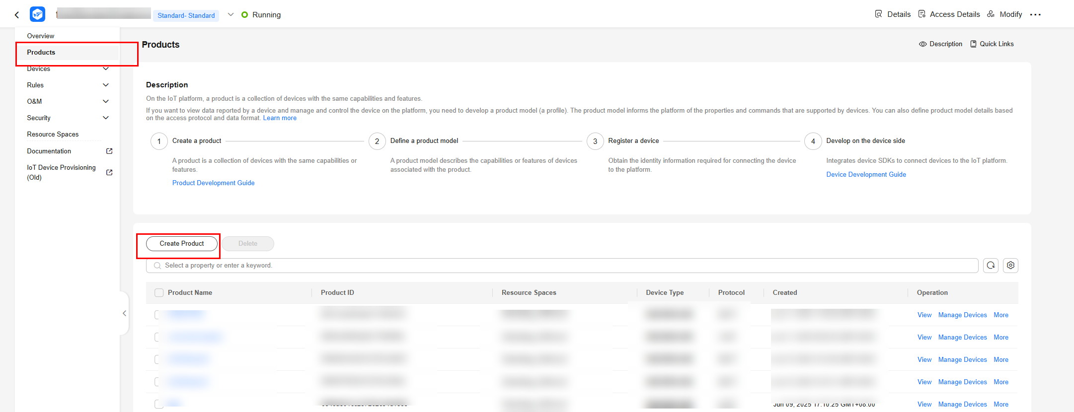
- Click Create Product to create a product using LwM2M over CoAP. Set the parameters and click OK.
Figure 2 Creating a product - CoAP
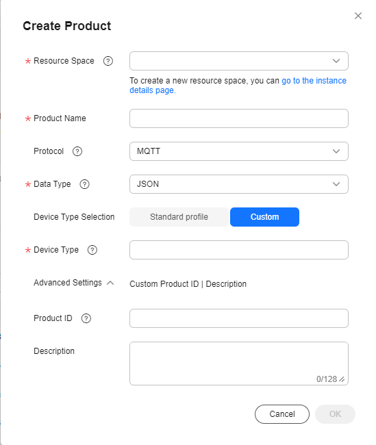
Basic Information
Resource Space
Select the resource space to which the product to create belongs.
Product Name
Customize a name, for example, Test_1.
Protocol
Select LwM2M over CoAP.
Data Type
Select Binary.
If Data Type is Binary, codec development is required for the product. If Data Type is JSON, codec development is not required.
Industry
Select Default.
Device Type
streetlamp
Defining a Product Model
- Click the name of the product created in 3 to go to the product details page.
- On the Model Definition tab page, click Customize Model to add a service for the product, and click OK.
- Service ID: Enter StreetLight.
- Service Type: You are advised to set this parameter to the same value as Service ID.
- Description: Provide a description, for example, "Define the properties of light intensity and status."
- Click the ID of the service added in 2. On the displayed page, click Add Property to define a light intensity property collected by the street light.
- Property Name: Enter light_intensity.
- Data Type: Select Integer.
- Access Permissions: Select Read and Write.
- Value Range: Set it to 0 to 100 (light intensity range).
Figure 3 Adding a property - light_intensity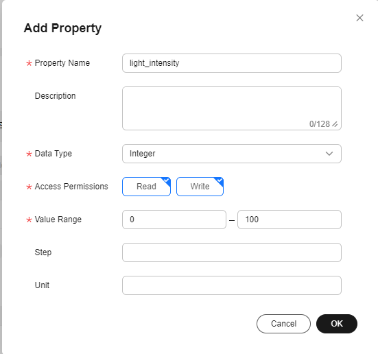
- Click Add Property to define a property as the status of the street light.
- Property Name: Enter light_status.
- Data Type: Select Integer.
- Access Permissions: Select Read and Write.
- Value Range: Set it to 0 or 1. 0 indicates that the light is turned off. 1 indicates that the light is turned on.
Figure 4 Adding a property - light_status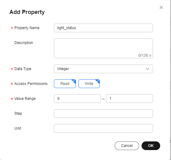
- Define the command used to remotely control the street light switch status.
- Click Add Command. In the dialog box displayed, set Command Name to SWITCH_LIGHT.
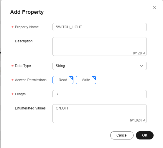
- Click Add Command Parameter. Set Parameter Name to SWITCH_LIGHT, Data Type to String, Length to 3, and Enumerated Value to ON,OFF. Click OK.
Figure 5 Adding a command parameter - SWITCH_LIGHT
- Click Add Response Parameter. Set Parameter Name to result and Data Type to Integer.
Figure 6 Adding a response parameter - result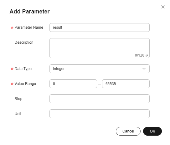
- Click OK. The product model of the street light is created.
Developing a Codec Online
For purposes of power conservation, devices generally report binary data. The codec converts the binary data into JSON data based on properties defined in the product model so that the platform and application can identify the data. When an application remotely delivers a command, the platform converts the command in JSON format into binary and delivers the binary data to the device.

If a device reports data in JSON format, you do not need to define a codec.
- On the product details page of the street light, click the Codec Development tab and click Develop Codec.
- Click Add Message and configure a data reporting message as follows to report street light data:
- Message Name: Enter LightData.
- Message Type: Select Data reporting.
- Add Response Field: Select this option. After a response field is added, the platform delivers the configured response data to the device when receiving data reported by the device.
- Response: Retain the default value AAAA0000.
Figure 7 Adding a message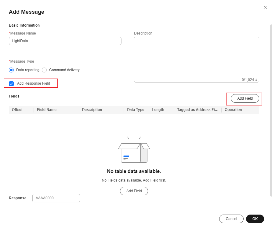
- Click Add Field to add the messageId field, which indicates the message type.
Figure 8 Adding a field - messageId

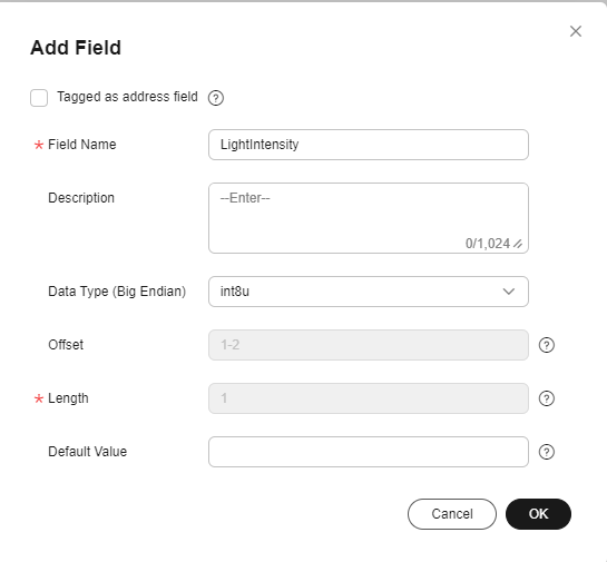
- Add the LightIntensity field to indicate the light intensity. Set Data Type to int8u (8-bit unsigned integer) and Length is 1.
Figure 9 Adding a field - LightIntensity
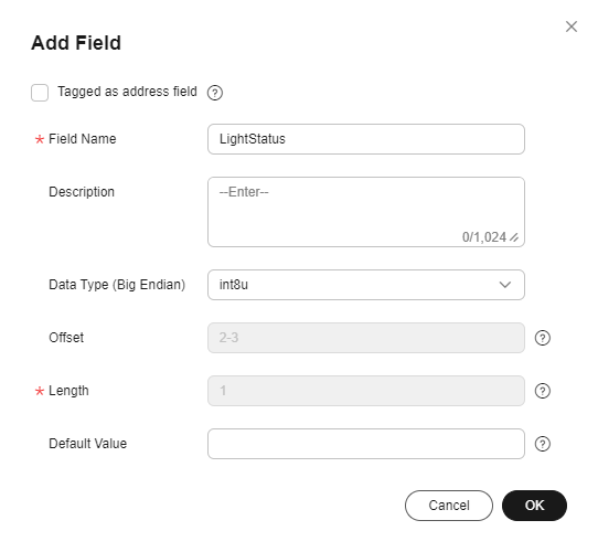
- Add the LightStatus field to indicate the street light switch status. Set Data Type to int8u (8-bit unsigned integer) and Length is 1.
Figure 10 Adding a field - LightStatus
- Click Add Message again to develop a codec for command delivery messages.
- Message Name: Enter SwitchStatus.
- Message Type: Select Command delivery.
- Add Response Field: Select this option. After a response field is added, the device reports the command execution result when receiving the command.
Figure 11 Adding a message - SwitchStatus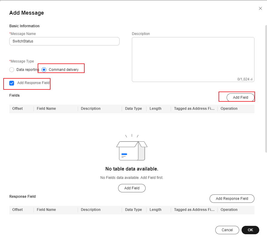
- Click Add Field to add the messageId field, which indicates the message type.
Figure 12 Adding a field - messageId

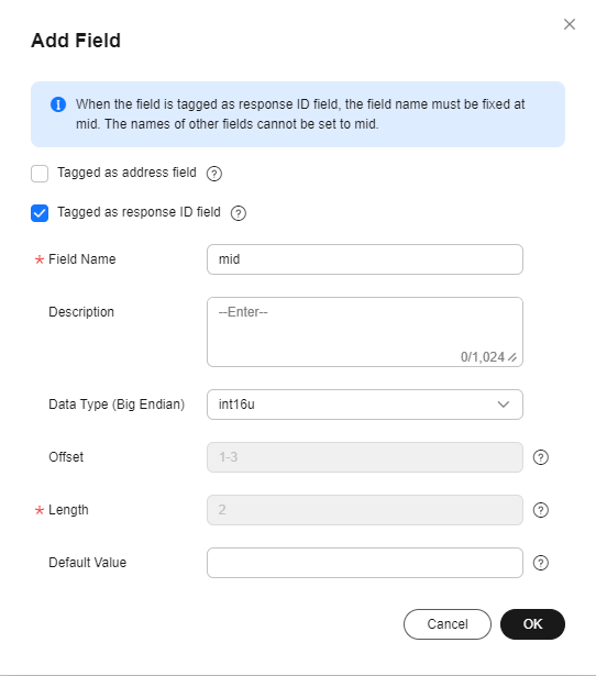
- Add the mid field to associate the delivered command with the command execution result.
Figure 13 Adding a command field - mid
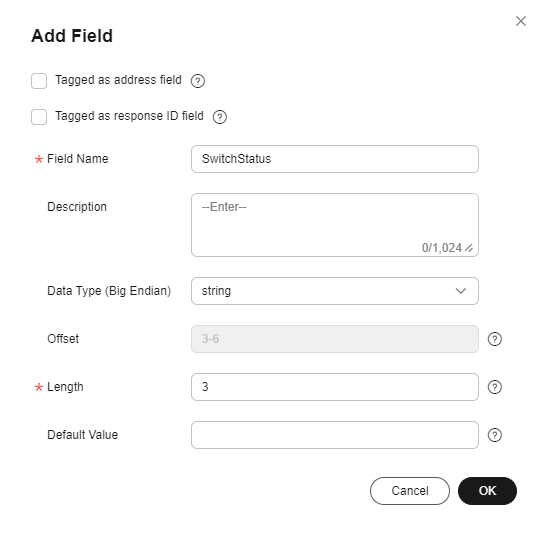
- Add the SwitchStatus field. Set Data Type to string and Length is 3.
Figure 14 Adding a command field - SwitchStatus
- Click Add Response Field to configure command delivery responses.
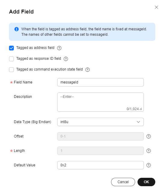
- Add the messageId field to indicate the message type. The command execution result is an upstream message, which is differentiated from the data reporting message by the messageId field.
Figure 15 Adding a response field - messageId
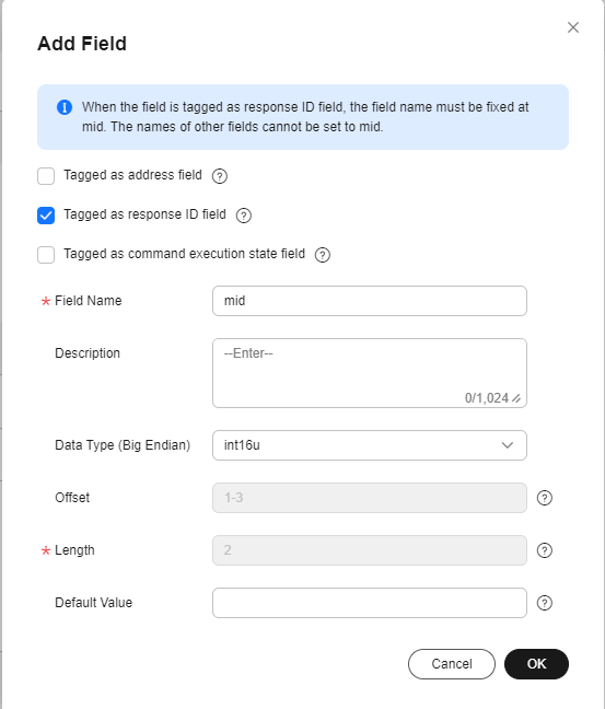
- Add the mid field to associate the delivered command with the command execution result.
Figure 16 Adding a response field - mid
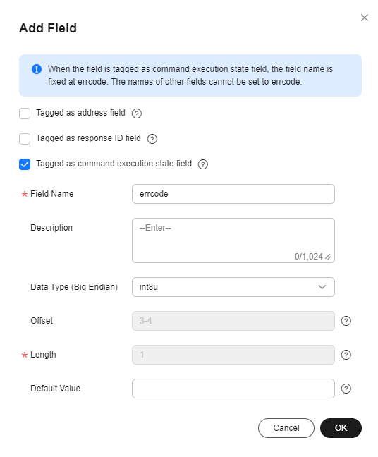
- Add the errcode field to indicate the command execution status. 00 indicates success and 01 indicates failure. If this field is not carried, the command is executed successfully by default.
Figure 17 Adding a response field - errcode
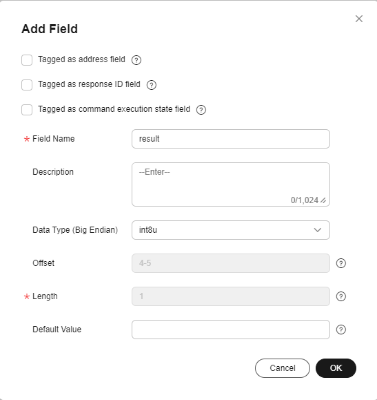
- Add the result field to indicate the command execution result.
Figure 18 Adding a response field - result
- Add the messageId field to indicate the message type. The command execution result is an upstream message, which is differentiated from the data reporting message by the messageId field.
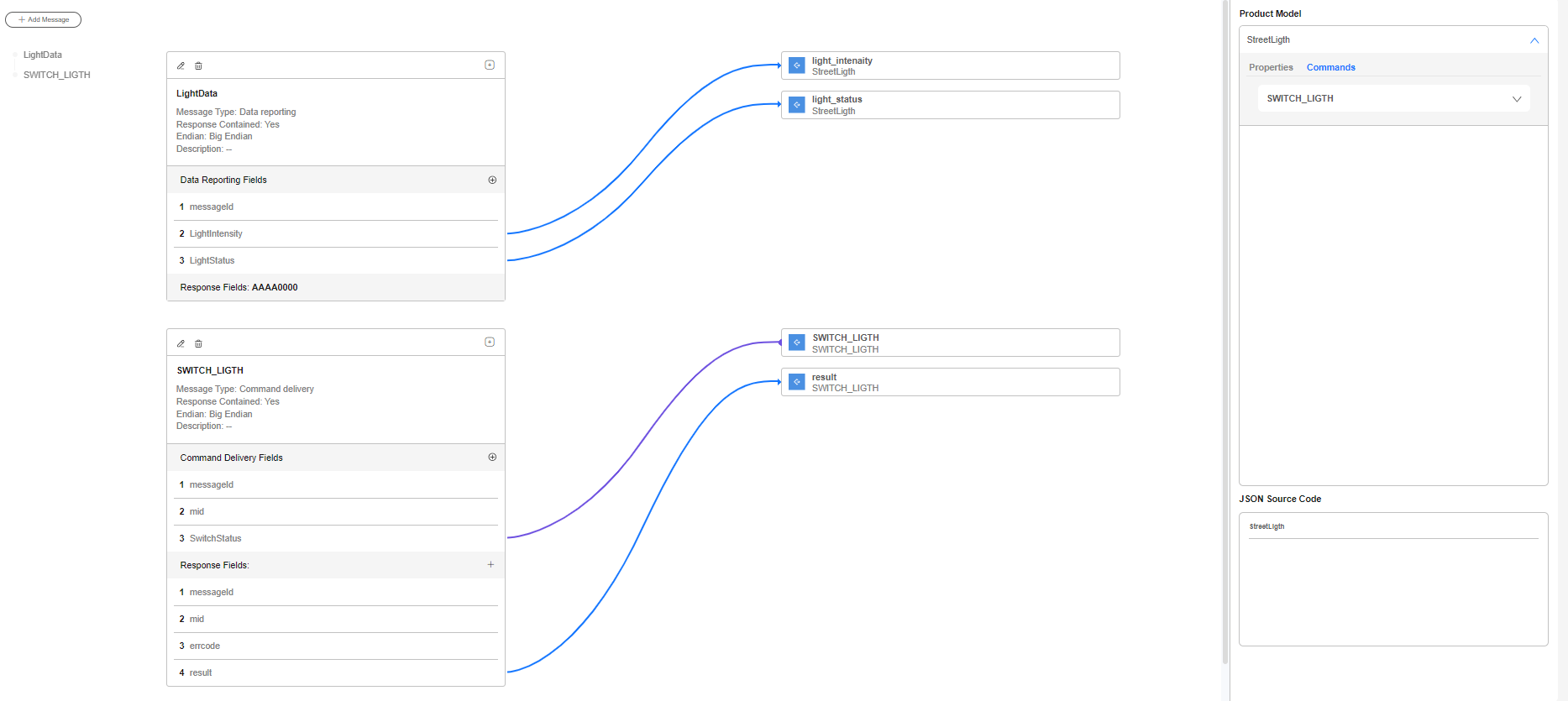
- Drag the property and command fields (defined in the product model) in the Product Model area on the right to map the fields in the data reporting and command delivery messages defined by the codec.
Figure 19 Developing a codec online
- Click Save in the upper right corner and click Deploy to complete codec deployment.
Debugging the Codec Online Using a Physical Device
Simulators debug the functions of devices and applications. You can debug the defined product model and codec by simulating data reporting and command delivery.
- On the product details page of the street light, click Online Debugging and click Add Test Device.
- In the dialog box displayed, set the parameters and click OK.
- Device Type: Select Physical device.
- Device Name: Customize a name.
- Node ID: Enter the IMEI of the device. The node ID will be carried by the device for device access authentication. You can view the node ID on the NB-IoT module.
- Secret: If DTLS is used for access, keep the secret secure.
Figure 20 Online debugging - Adding a test device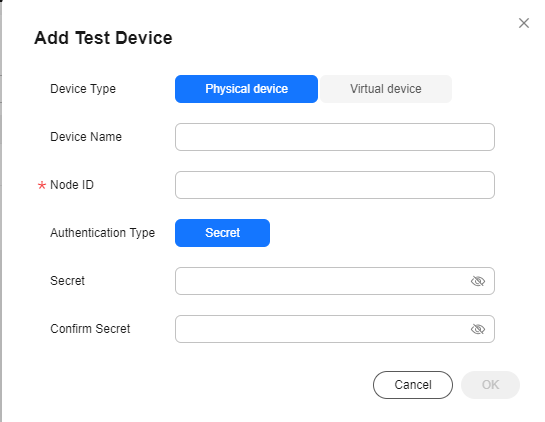

The newly added device is in the inactive state. In this case, online debugging cannot be performed. For details, see Device Connection Authentication. After the device is connected to the platform, perform the debugging.
- Click Debug to access the debugging page.
Figure 21 Entering debugging

- Simulate a scenario where a control command is remotely delivered. In Application Simulator, set Service to StreetLight, Command to SWITCH_LIGHT, and Command Value to ON, and click Send. The street light is turned on.
Debugging the Codec Online Using a Virtual Device
- On the product details page of the street light, click Online Debugging and click Add Test Device.
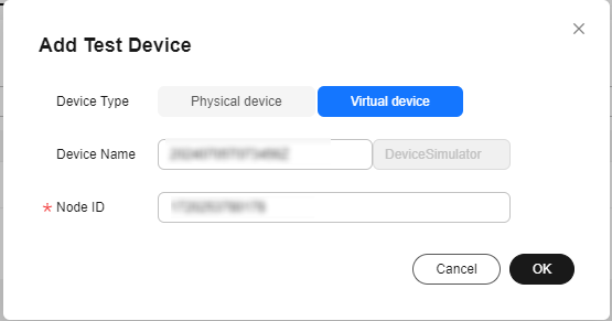
- In the dialog box displayed, select Virtual device and click OK. The virtual device name contains DeviceSimulator. Only one virtual device can be created for each product.
Figure 22 Online debugging - Creating a virtual device
- Click Debug to access the debugging page.
Figure 23 Entering debugging

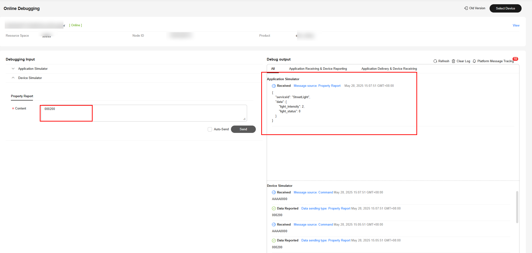
- Simulate a data reporting scenario. Specifically, under Device Simulator, enter the hexadecimal code stream 002000, and click Send. (The first byte 00 indicates the message ID, the second byte 20 indicates the light intensity, and the third byte 00 indicates the switch status.) Under Application Simulator, "Light_Intensity": 32, "Light_Status": 0 (converted JSON data) should be displayed.
Figure 24 Online debugging - Simulating data reporting
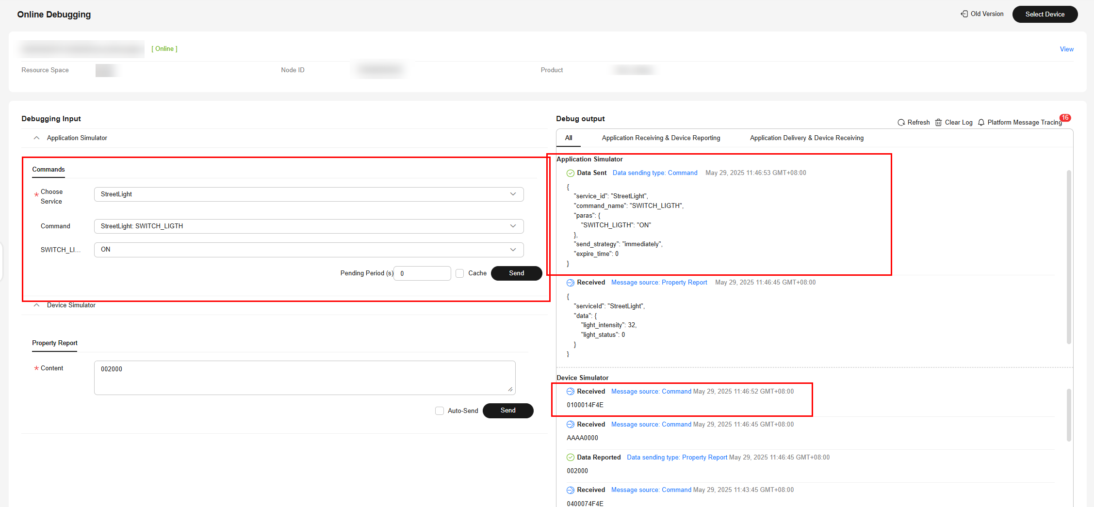
- Simulate a command delivery scenario. Specifically, under Application Simulator, select StreetLight for Service, SWITCH_LIGHT for Command, ON for SWITCH_LIGHT, and click Send. Under Device Simulator, 0100014F4E (hexadecimal number converted from the ASCLL code) should be displayed.
Figure 25 Online debugging - Simulating command delivery
Debugging Using an Offline Simulator
The NB-IoT device simulator is used to simulate the access of NB-IoT devices (devices using LwM2M over CoAP) to the platform for data reporting and command delivery.
- Obtain the node ID and secret generated during device registration in 2.
- Download and decompress the NB-IoT device simulator, and double-click NB-IoTDeviceSimulator_zh.jar to run the simulator.

- The simulator can run on Windows, but not macOS.
- Ensure that the JDK has been installed. Otherwise, the JAR file cannot be executed.

The package contains the following files:
- NB-IoTDeviceSimulator_en.jar: simulator
- Californium.properties: simulator configuration file
- setting.properties: configuration file for connecting the simulator to the platform
- When a message is displayed requesting you to confirm whether to enable DTLS encrypted transmission, click No if a secret is not entered during device registration, or Yes if a secret is entered.

- Enter IP address, VerifyCode, and psk, and click Register Device to bind the simulator to the platform.
Note: If DTLS encryption transmission is disabled, you do not need to enter a PSK.
Set the three parameters as follows:- IP address: access domain name displayed on the IoTDA console. (You can also use the IP address. You can run the ping [domain name] command to obtain the IP address.)
- VerifyCode: device ID, for example, aaaaa11111.
- psk: secret set during device registration, for example, *******.

On the IoTDA console, choose and view the device status. If the device is displayed as Online, the simulator is bound to the platform.
- Simulate a data reporting scenario. Specifically, under the NB-IoT device simulator, enter the hexadecimal code stream 001400, and click Send Data. (The first byte 00 indicates the message ID, the second byte 14 indicates the light intensity, and the third byte 00 indicates the switch status.)
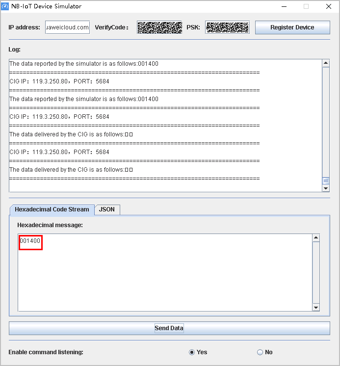
The data is reported successfully. You can return to the console and view the latest reported data on the device details page of aaaaa11111. The latest reported data is "Light_Intensity": 20, "Light_Status": 0.
- Simulate the remote command delivery scenario. On the console, locate the target product and click the product to go to the product details page. Click the Online Debugging tab and click Debug of the aaaaa11111 device.
Under Application Simulator, select StreetLight for Service, SWITCH_LIGHT for Command, ON for SWITCH_LIGHT, and click Send.
The data delivered by the CIG is ON in the log area, and the simulator displays a message indicating that the downstream message from the platform is received and asking whether to respond. Click Yes. On the Application Simulator page of the IoTDA console, you can see that the command is in the Delivered state.
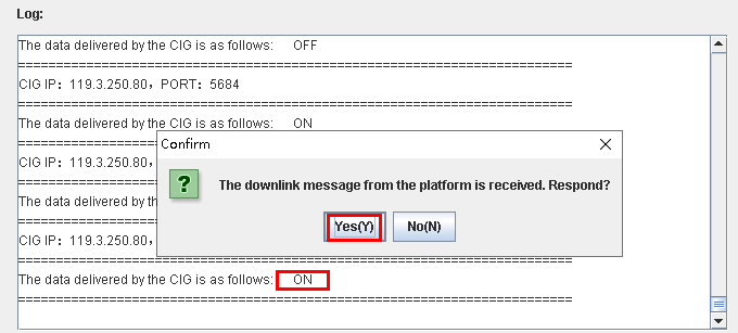

Strings are parsed using ASCII in the codec. You need to deliver printable characters. Non-printable characters are not displayed in the simulator.
Feedback
Was this page helpful?
Provide feedbackThank you very much for your feedback. We will continue working to improve the documentation.See the reply and handling status in My Cloud VOC.
For any further questions, feel free to contact us through the chatbot.
Chatbot


