
Advanced Case Status
You can customize case statuses on the Case Status page during case handling.
Prerequisites
- You have the Case Configuration permission.
- The Case 2.0 feature has been enabled for the tenant space.
- The system parameter AICC__IsEnablingCaseBPM has been set to True on the Config > Setup > Parameters > System Parameters page of AppCube by the system administrator.
Procedure
- Sign in to the AICC and choose .
- Click and enter a status name. Figure 1 Create page

Table 1 Parameters for creating a status Parameter
Description
Remarks
Organization
- After the tenant parameter Has the tenant enabled inter-organization data isolation enforcement is set to Yes, use either of the following methods to configure the OU data scope based on site requirements:
- For accounts without the View All Organization Data permission under System Public Permissions configured:
- If the Viewing and Editing Home Organization Data and View Lower-Level Organization Data permissions under System Public Permissions are not configured, only the OUs specified by Accessable Organizations configured on the Employee Info or Organization Unit page can be selected. NOTE:
If accessible OUs are configured on the Employee Info or Organization Unit page, the accessible OU configuration permission on the Employee Info page is used.
- If the Viewing and Editing Home Organization Data permission under System Public Permissions is configured, the OU (excluding sub-OUs) to which the current business account belongs can be viewed.
- If the View Lower-Level Organization Data permission under System Public Permissions is configured, the sub-OUs of the OU to which the current business account belongs can be viewed.
- If the Viewing and Editing Home Organization Data and View Lower-Level Organization Data permissions under System Public Permissions are not configured, only the OUs specified by Accessable Organizations configured on the Employee Info or Organization Unit page can be selected.
- For accounts with the View All Organization Data permission under System Public Permissions configured, all OUs can be selected.
- The number of OUs that can be selected is specified by the value of the system-level parameter Maximum number of OU organizational unit queries on the page.
- For accounts without the View All Organization Data permission under System Public Permissions configured:
- After the tenant parameter is set to No, all OUs can be selected.
-
Template
Select a preset status template or a customized template.
- A preset template cannot be edited.
- A customized template can be edited again after being disabled.
Name
Status name.
-
Description
Description.
-
- After the tenant parameter Has the tenant enabled inter-organization data isolation enforcement is set to Yes, use either of the following methods to configure the OU data scope based on site requirements:
- Click .
- Click the status name to go to the Configuration Process page.
- Click
 to disable the process. The disabled process can be edited again. Figure 2 Configuration Process page
Table 2 Fill In diagram element parameter Parameter
Description
Participants
This parameter can be set to Portal User or Queue.
- Portal User: all users in the current tenant space.
- Queue: case queue. For details, see Case Queue. After a user in the selected queue accepts a case, other users cannot accept the case.
Table 3 Dispatch diagram element parameter Parameter
Description
Participants
This parameter can be set to Portal User or Queue.
- Portal User: all users in the current tenant space.
- Queue: case queue. For details, see Case Queue. After a user in the selected queue accepts a case, other users cannot accept the case. NOTE:
The Dispatch diagram element can be connected to multiple diagram elements.
Table 4 Approval diagram element parameters Parameter
Description
Participants
This parameter can be set to Portal User or Queue.
- Portal User: all users in the current tenant space.
- Queue: case queue. For details, see Case Queue. After a user in the selected queue accepts a case, other users cannot accept the case.
Who can approve?
- One of selected members: The approval process ends after any recipient completes the approval, and other users do not need to perform the approval operation.
- All assignees in parallel: Each user needs to complete the approval. The approval process ends after the percentage of the number of users completing the approval is greater than the threshold.
Percentage
This parameter is displayed only when Who can approve? is set to All assignees in parallel.
If this threshold is reached, the approval result with more votes is executed.
Default Outcome
This parameter is displayed only when Who can approve? is set to All assignees in parallel. Possible values are as follows:
- reject
- approve
Outcome Trigger Type
This parameter is displayed only when Who can approve? is set to All assignees in parallel. The options are as follows:
- Continue immediately when votes are satisfied: The voting result is triggered immediately when the threshold is reached.
- Wait for all votes completed: The voting result is triggered after all users complete the approval.
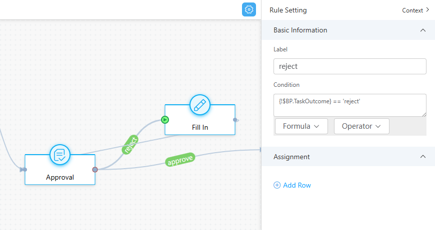
Connecting line
- For the approve connecting line, as shown in Figure 4, enter {!$BP.TaskOutcome} == 'approve' in the Condition text box.
- For the reject connecting line, as shown in Figure 3, enter {!$BP.TaskOutcome} == 'reject' in the Condition text box.
- When the approval node starts, an approver needs to go to the case details page to complete the approval.
- After the configuration is completed, click
 to enable the status.
 - Create a case type by performing the following operations: Choose Configuration Center > Case Configuration 2.0 > Case Configuration > Case Type, click Create, set parameters, and click Save. You can select the new advanced case status enabled in the previous step.
- Choose and click Create. Select the case type created in 7 and click
 . The case is processed based on the status configured in 5. Figure 5 Case Node page

Feedback
Was this page helpful?
Provide feedbackThank you very much for your feedback. We will continue working to improve the documentation.See the reply and handling status in My Cloud VOC.
For any further questions, feel free to contact us through the chatbot.
Chatbot


