Configuration on the Hillstone Firewall
Prerequisites
The basic network configuration of the Hillstone firewall has been completed.
Procedure
- Log in to the configuration page.
A firewall running the 5.5R9 version is used as an example. The configuration pages may vary according to the firewall models and software versions.
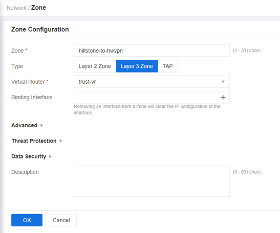
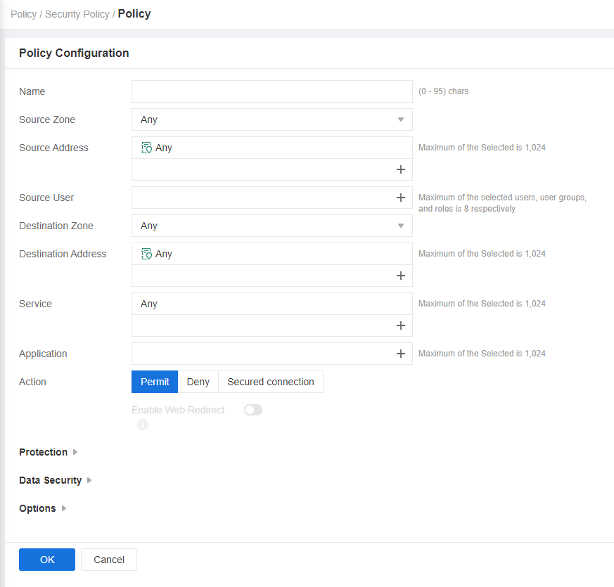
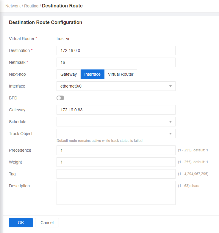
- Complete basic settings.
- Configure VPN connections.
- Choose . On the IPsec VPN tab page, click New.
- Click the plus sign (+) in the Peer Name drop-down list box to add peer information.
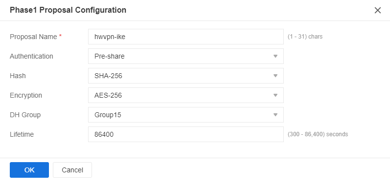
- Click the plus sign (+) in the Proposal1 drop-down list box to create a phase-1 proposal. Set parameters and click OK. Figure 4 shows the key parameter settings.
- Configure VPN peers. As the Huawei Cloud VPN gateway has two EIPs bound, you need to configure two peers.
Select the phase-1 proposal created in c from the Proposal1 drop-down list box. Click Advanced Configuration, toggle on NAT Traversal and DPD, and click OK.
Figure 5 Configuring VPN peers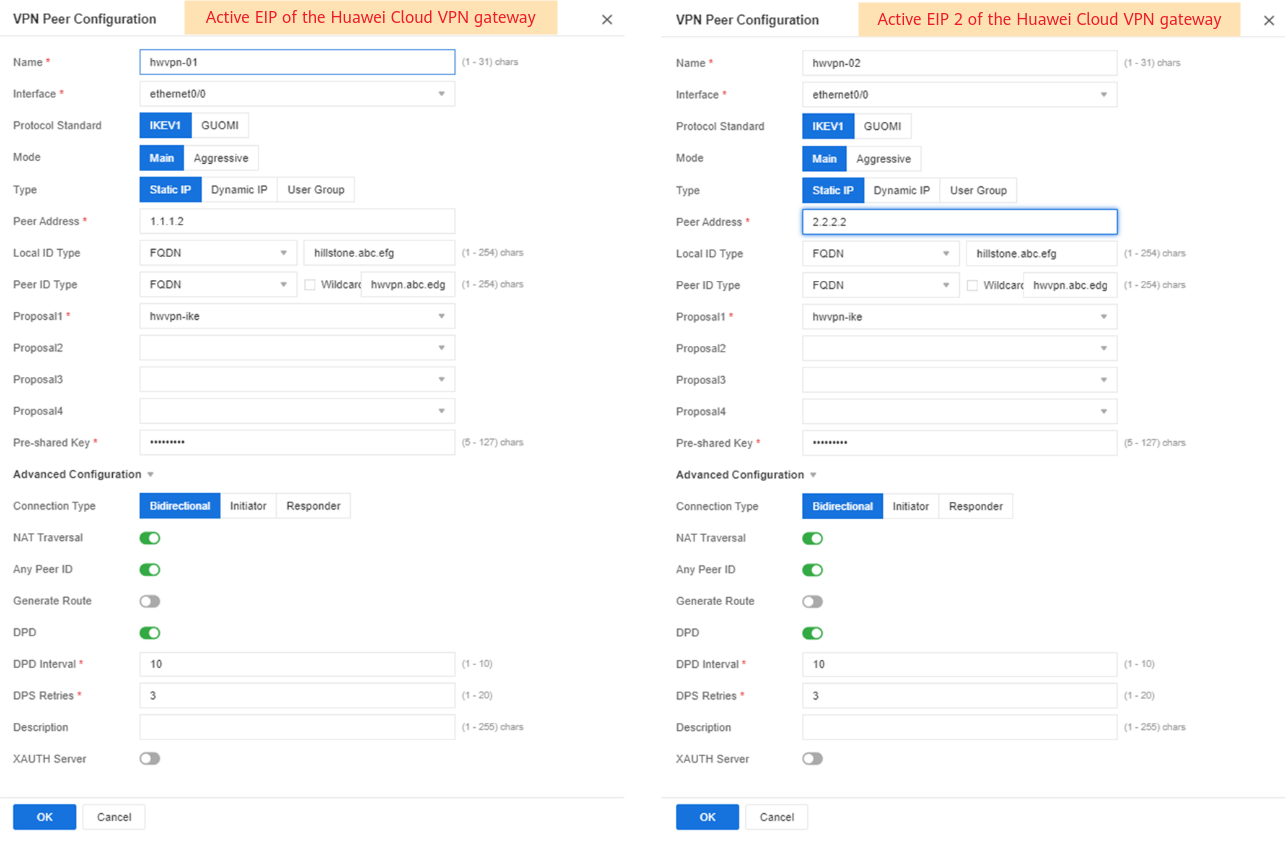
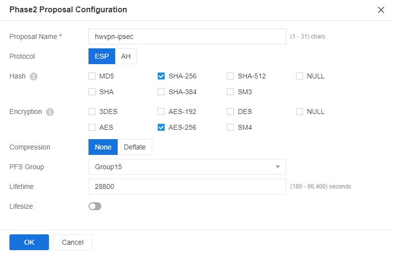
- Click the plus sign (+) in the P2 Proposal drop-down list box to create a phase-2 proposal. Set parameters and click OK. Figure 6 shows the key parameter settings.
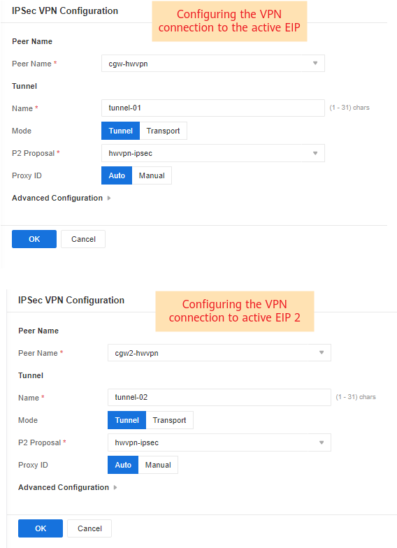
- Configure VPN connection information. Select each of the VPN peers created in d from the Peer Name drop-down list box, select the phase-2 proposal created in e from the P2 Proposal drop-down list box, and click OK.
Figure 7 Configuring IPsec VPN
- Configure tunnel interfaces.
- Choose , click New, and choose Tunnel Interface.
- Configure two tunnel interfaces. Figure 8 shows the key parameter settings.
- Configure BGP.
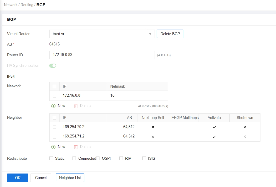
Choose , and complete the BGP configuration, as shown in Figure 9.
Set Router ID to the gateway address of the downlink private network interface on the Hillstone firewall, Network to the CIDR block of the on-premises data center, and Neighbor to each of the two peer tunnel interfaces.
Feedback
Was this page helpful?
Provide feedbackThank you very much for your feedback. We will continue working to improve the documentation.See the reply and handling status in My Cloud VOC.
For any further questions, feel free to contact us through the chatbot.
Chatbot

