

Enabling NAT Gateway Traffic Protection
Scenario
If ECSs or other resources in a VPC connect to the Internet through the NAT gateway, they are exposed to security risks, such as unauthorized access, data leakage, and malicious attacks. To address these risks, CFW protects the traffic between service VPCs and NAT gateways, blocking unauthorized outbound connections and malicious traffic. It also supports fine-grained access control based on private IP addresses to block unauthorized traffic access.
This section describes how to enable protection for NAT gateway traffic using a VPC border firewall.
If service traffic is routed to the Internet through an EIP, enable protection by referring to Enabling Internet Border Traffic Protection.
What Is NAT Gateway Traffic?
NAT gateway traffic refers to the traffic between a NAT gateway and the Internet. It can be protected in two scenarios:

- Protecting a NAT gateway through an EIP
If the EIP bound to the NAT gateway is used to connect to the Internet, CFW protects all traffic passing through the NAT gateway. This is suitable for coarse-grained protection.
Whether outbound traffic from a VPC undergoes network address translation via a NAT Gateway to access the internet through an EIP, or inbound internet traffic is distributed by a NAT Gateway to cloud servers, enabling protection on CFW for the gateway-bound EIP alters enforcement. Once protection is active and policies are applied to the EIP, CFW inspects all traffic traversing that EIP against your access control rules and security engines.
This EIP protection mode applies only to large-grained overall management and control. All traffic passing through the NAT Gateway is managed and controlled in a unified manner.
- Protecting a NAT gateway through a VPC
To achieve granular control over diverse service types, you can deploy a VPC border firewall and leverage ER to position CFW between the NAT Gateway VPC and your service VPCs. This setup enables precise management of private IP traffic, making it ideal for users with complex environments and strict security audit requirements.
Private network traffic routes from the service VPC through ER to CFW. CFW inspects the traffic against your protection policies, forwards approved traffic back to ER, and then directs it to the NAT Gateway.
By configuring tailored NAT protection policies for distinct service assets, this private IP protection method minimizes your attack surface and limits external exposure. Furthermore, it logs private IP traffic to simplify source tracing and audit, making it highly effective for complex enterprise deployment models.
During this process, CFW relies on ER for the following reasons:
- Decoupling: ER operates as an independent routing hub. CFW connects via logical attachments without directly altering inner-VPC route tables, minimizing disruption to your existing network topology.
- Scalability: A single ER can aggregate multiple VPCs and firewall instances, supporting complex, enterprise-grade topologies.
- Reliability: ER supports cross-AZ high availability, providing native redundancy for critical traffic paths.
This architecture treats CFW as a specialized connection type within ER. Traffic from the VPC is steered to the firewall for inspection via an associated route table, and permitted traffic is distributed to the NAT Gateway via a propagation route table. This delivers fine-grained control based on the original private IP addresses, making the solution perfectly suited for multi-VPC aggregation and hybrid cloud interconnections.
Introduction to NAT Gateway Traffic Protection
Networking
SNAT and DNAT networking diagrams are as follows.

- SNAT
SNAT protection provides fine-grained access control for outbound access. It is suitable if the VPC of the NAT gateway is isolated from the service VPC, and multiple VPCs or subnets use EIPs to access the Internet.
After an ECS initiates an outbound access request, the traffic is forwarded to the firewall through the enterprise router. The firewall blocks or allows the traffic based on SNAT protection rules, and forwards secure traffic to the enterprise router. The enterprise router forwards the traffic to the NAT gateway, which then forwards the traffic to the Internet based on SNAT rules.
- DNAT
DNAT provides fine-grained access control for the access from the Internet to internal resources. It is suitable if the VPC of the NAT gateway is isolated from the service VPC, and multiple VPCs or subnets use the NAT gateway to receive access from the Internet.
After the Internet initiates access to an internal resource, the traffic is forwarded to the enterprise router based on the DNAT rule of the NAT gateway. The enterprise router forwards the traffic to the firewall. The firewall blocks or allows the traffic based on DNAT protection rules, and forwards secure traffic to the enterprise router, which then forwards the traffic to the service VPC.
Impacts on Services
Before enabling VPC protection, check whether there is any protection rule or blacklist that blocks all traffic.
- If protection is enabled for a VPC, such a protection rule or blacklist will take effect and block all the traffic of the VPC. This may interrupt services. Before enabling protection, check for persistent connections and services that do not support session reestablishment. If any, handle them first.
For details about how to edit a protection rule, see Managing Protection Rules. For details about how to edit a blacklist, see Managing the Blacklist and the Whitelist.
- If there is no protection rule or blacklist that blocks all traffic, enabling or disabling VPC protection will not interrupt services.
Constraints
- Only the professional edition supports NAT gateway traffic protection.
- Traffic diversion depends on the enterprise router.
In the VPC route table, when you configure the route with the enterprise router as the next hop, do not specify the default CIDR block 0.0.0.0/0. If an ECS in the VPC has an EIP bound, the VPC route table will have a policy-based route with the default CIDR block as the destination. This route has a higher priority than the route with the enterprise router as the next hop. In this case, traffic is forwarded to the EIP and cannot reach the enterprise router. Therefore, do not set the destination of a route (with an enterprise router as the next hop) to 0.0.0.0/0 in the VPC route table if the following conditions are met. Otherwise, some service traffic cannot be forwarded to the enterprise router.
- An ECS in the VPC has an EIP bound.
- The VPC has ELB, NAT Gateway, VPCEP, or DCS deployed.
For details about how to configure routes in the preceding scenario, see Why Traffic Can't Be Forwarded from a VPC with a Route Destination of 0.0.0.0/0 to Its Enterprise Router?
- By default, CFW supports standard private CIDR blocks. To configure other CIDR blocks, modify private CIDR blocks or add private CIDR blocks. Otherwise, CFW may fail to forward traffic between VPCs.
- To let the DNAT gateway divert east-west traffic to the CFW cluster and configure DNAT rules, submit a service ticket to ask service O&M personnel to upgrade CFW. The old version does not support DNAT functions and may cause traffic loss.
Enabling NAT Gateway Traffic Protection
A firewall has been created. For details, see Creating a VPC Border Firewall.
Step 1: Connect VPC1 and VPC-NAT to an Enterprise Router
- Add VPC connections. For details, see Adding VPC Attachments to an Enterprise Router.

Two connections need to be added. Set their Attached Resource to VPC1 and VPC-NAT, respectively.
- Create two route tables.
- In the upper left corner, click
 and choose Networking > Enterprise Router. Click Manage Route Table.
 - Create an association route table and a propagation route table, used for connecting to a protected VPC and a firewall, respectively.
On the enterprise router details page, click the Route Tables tab. On the route table configuration page, click Create Route Table. In the displayed dialog box, configure parameters.
Table 1 Route table parameters Parameter
Description
Example Value
Name
Route table name.
It must meet the following requirements:- Must contain 1 to 64 characters.
- Can contain letters, numbers, underscores (_), hyphens (-), and periods (.).
er-rtb-01
AS_Path Route Selection
(Optional)
- Do not configure: The system compares AS_Path attributes for the routes during load balancing and prefers the route with the shortest AS_Path length. The AS_Path attribute records all AS numbers that a BGP route passes through from the local end to the destination in the vector order. The fewer the AS numbers recorded in the AS_Path attribute, the shorter the AS_Path length.
- Ignore same length AS_Path: The system skips comparing the AS_Path attributes during load balancing if their lengths are identical. AS_Path prevents BGP loops between ASs. If you select this option, there may be BGP loops.
Do not configure
Tag
(Optional)
During the route table creation, you can tag the route table resources. Tags identify cloud resources for purposes of easy categorization and quick search.
For details about tags, see Tag Overview.
Tag key: test
Tag value: 01
Description
(Optional)
Route table description.
-
- In the upper left corner, click
- Configure the association route table.
- Create associations to VPC1 and VPC-NAT. On the route table configuration page, click the Associations tab and click Create Association. For more information, see Table 2.
Two associations need to be created. Set their Attachment to the VPC1 and VPC-NAT attachments, respectively.
- Add a static route to the firewall. Click the Routes tab and click Create Route. For more information, see Table 3. Figure 3 Creating a route
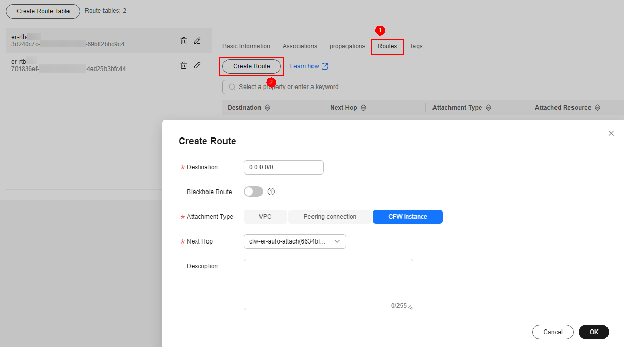
Table 3 Route parameters Parameter
Description
Destination
Set the destination address.
- If 0.0.0.0/0 is configured, all the traffic (IPv4) of the VPC is protected by CFW.
- If a CIDR block is configured, the traffic of the CIDR block is protected by CFW.
Blackhole Route
You are advised to disable this function. If it is enabled, the packets from a route that matches the destination address of the blackhole route will be discarded.
Attachment Type
Set Attachment Type to CFW instance.
Next Hop
Select the automatically generated firewall attachment cfw-er-auto-attach.
Description
(Optional) Description of a route.
- Create associations to VPC1 and VPC-NAT. On the route table configuration page, click the Associations tab and click Create Association. For more information, see Table 2.
- Configure the propagation route table.
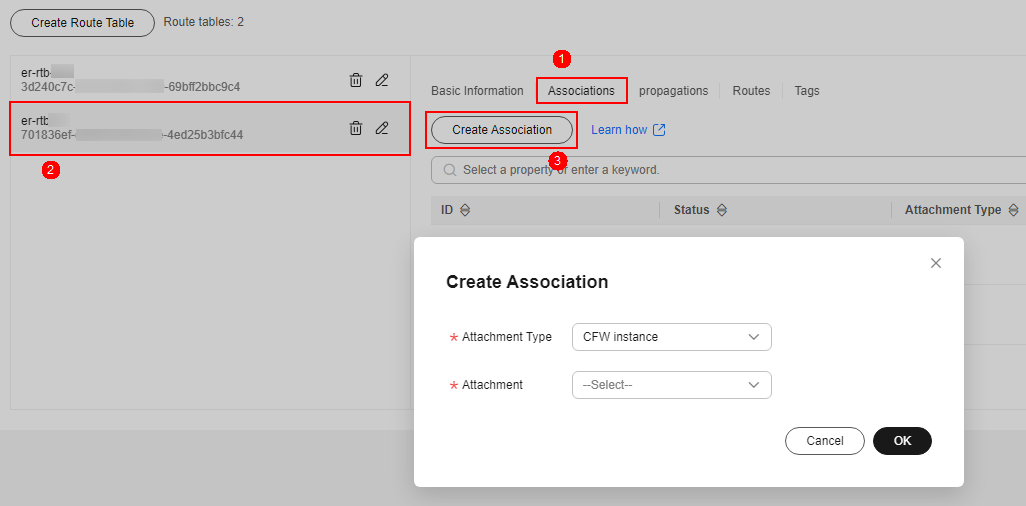
- Add an association with the firewall. On the route table configuration page, click the Associations tab and click Create Association. For more information, see Table 4. Figure 4 Creating an association
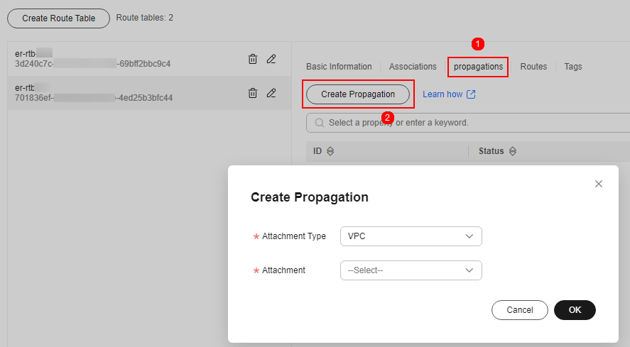
- Create a propagation for VPC1. On the route table setting page, click the Propagations tab and click Create Propagation. For more information, see Table 5. Figure 5 Creating a propagation
- Add a static route to VPC-NAT. Click the Routes tab and click Create Route. For more information, see Table 6.
Table 6 Route parameters Parameter
Description
Destination
Set it to 0.0.0.0/0.
Blackhole Route
You are advised to disable this function. If it is enabled, the packets from a route that matches the destination address of the blackhole route will be discarded.
Attachment Type
Select VPC.
Next Hop
Select the VPC-NAT attachment from the drop-down list.
- Add an association with the firewall. On the route table configuration page, click the Associations tab and click Create Association. For more information, see Table 4.
Step 2: Configure a NAT Gateway
- Add an SNAT rule.
- Return to the Enterprise Router page. In the navigation pane of Network Console, choose NAT Gateway > Public NAT Gateways.
- Click the name of a public network NAT gateway. The Basic Information tab is displayed. Click the SNAT Rules tab.
- Click Add SNAT Rule. For details, see Table 7.
Table 7 Adding an SNAT rule Parameter
Description
Scenario
Scenario where the SNAT rule is used. Select VPC.
CIDR Block
Select Custom to enable servers in this subnet to use the SNAT rule to access the Internet.
- Custom: Customize a CIDR block or enter the IP address of a VPC.
Public IP Address Type
Select EIP, which is an EIP for Internet access.
You can select only an EIP that is not bound to any resource, an EIP that is bound to a DNAT rule whose Port Type is not set to All ports in the current public NAT gateway, or an EIP that is bound to an SNAT rule of the current public NAT gateway.
You can select multiple EIPs at once. Up to 20 EIPs can be selected for each SNAT rule. If you have selected multiple EIPs for an SNAT rule, one EIP will be chosen randomly.
Monitoring
Monitoring of the number of SNAT connections.
You can set alarm rules to monitor your SNAT connections and keep informed of any changes in a timely manner.
Description
Supplementary information about the SNAT rule. Enter up to 255 characters.
- Click OK.
- Configure the VPC-NAT route table.
- In the service list, click Virtual Private Cloud under Networking. In the navigation pane, choose Route Tables.
- In the Name column, click the route table name of the VPC corresponding to the NAT gateway. The Summary page is displayed.
- Click Add Route. For details, see Table 8.
Table 8 Route parameters Parameter
Description
Destination Type
Select IP address.
Destination
Destination CIDR block. Enter the IP address of VPC1.
The CIDR block cannot conflict with existing routes or subnet CIDR blocks in the VPCs.
Next Hop Type
Select Enterprise Router from the drop-down list.
Next Hop
Select a resource for the next hop.
The enterprise routers you created are displayed in the drop-down list.
Description
(Optional) Supplementary information about the route.
Enter up to 255 characters. Angle brackets (< or >) are not allowed.
- Click OK.
Step 3: Configure a route table for VPC1
- Return to the Route Tables page and click the route table name of VPC1. The Summary page is displayed.
- Click Add Route. For details, see Table 9.
Table 9 Route parameters Parameter
Description
Destination Type
Select IP address.
Destination
Destination CIDR block. Set it to 0.0.0.0/0.
Next Hop Type
Select Enterprise Router from the drop-down list.
Next Hop
Select a resource for the next hop.
The enterprise routers you created are displayed in the drop-down list.
Description
(Optional) Supplementary information about the route.
Enter up to 255 characters. Angle brackets (< or >) are not allowed.
- Click OK.
Step 4: Enable a VPC Border Firewall
- Return to the CFW console.
- In the navigation pane, choose Assets > Inter-VPC Border Firewalls.
- Click the
 next to Firewall Status and click OK in the displayed dialog box to enable the VPC border firewall.
Follow-up Operations
Once NAT gateway traffic protection is enabled, your service traffic is routed through CFW. By default, all traffic is allowed. You can monitor traffic trends or configure access control and attack defense policies to gain better control over your traffic.
- View traffic trends and logs.
- View the traffic trends and statistics of CFW. For details, see Traffic Center.
- View all traffic logs of CFW. For details, see Viewing Traffic Logs.
- Configure protection rules for refined traffic control.
After protection is enabled, all traffic is allowed by default. CFW will block traffic based on the policies you configure.
- Allow or block traffic using protection rules. For details, see Configuring Protection Rules to Block or Allow VPC Border Traffic.
- Allow or block traffic using the blacklist and whitelist. For details, see Adding Blacklist or Whitelist Items to Block or Allow VPC Border Traffic.
- Defend against network attacks: Configure intrusion prevention to handle network attacks. For details, see Configuring Basic IPS Protection.
Related Operations
Disabling NAT gateway traffic protection: If your workloads no longer require NAT gateway traffic protection, you can disable this feature. For details, see Disabling a VPC Border Firewall.
What is your overall rating for this page?
Thank you very much for your feedback. We will continue working to improve the documentation.See the reply and handling status in My Cloud VOC.
For any further questions, feel free to contact us through the chatbot.
Chatbot


