
Cloud Native Network 2.0
Model Definition
Cloud Native Network 2.0 is a proprietary, next-generation container network model that combines the elastic network interfaces (ENIs) and supplementary network interfaces (sub-ENIs) of the Virtual Private Cloud (VPC). This allows ENIs or sub-ENIs to be directly bound to pods, giving each pod its own unique IP address within the VPC. Furthermore, it supports additional features like ELB passthrough container, pod binding to a security group, and pod binding to an EIP. Because container tunnel encapsulation and NAT are not required, Cloud Native Network 2.0 enables higher network performance than the container tunnel network model and VPC network model.
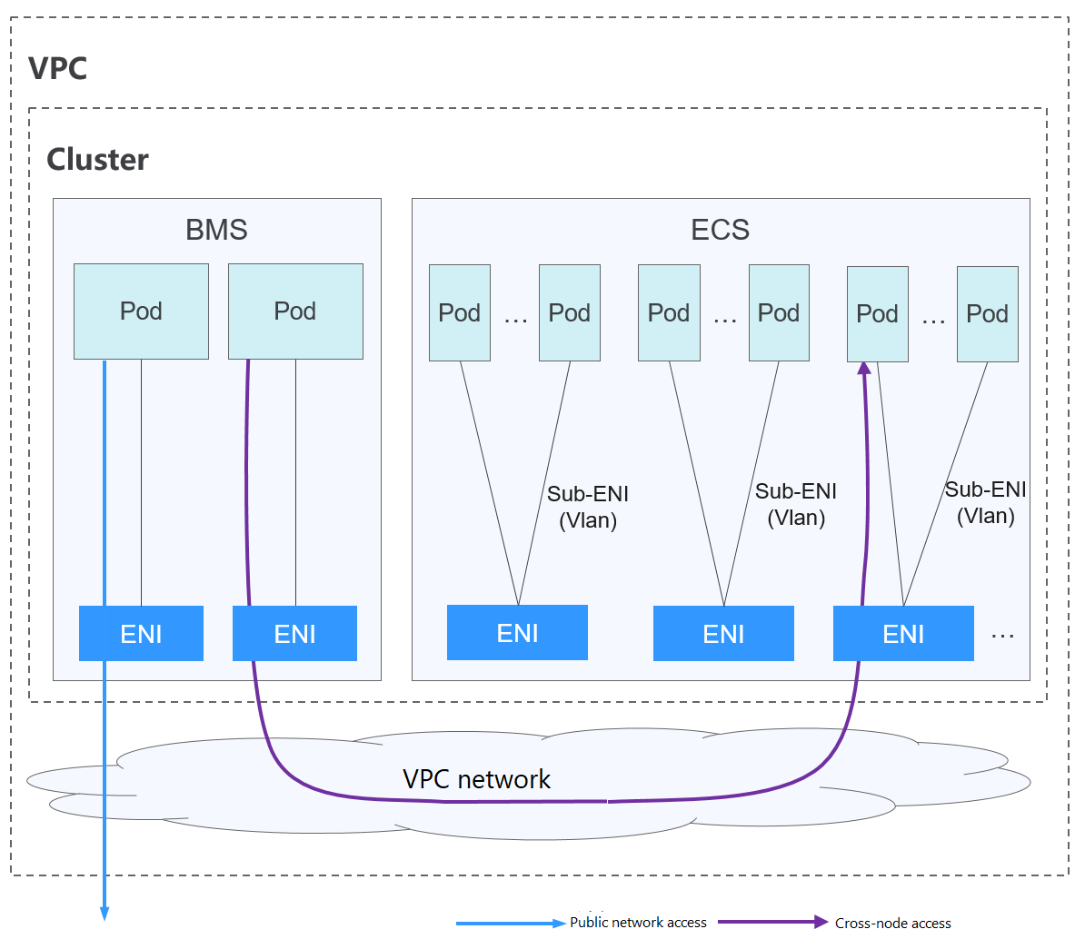
In a cluster using Cloud Native Network 2.0, pods rely on ENIs or sub-ENIs to connect to external networks.
- Pods running on ECS nodes use sub-ENIs that are bound to the ECS' ENIs through VLAN sub-interfaces.
- To run a pod, it is necessary to bind ENIs to it. The number of pods that can run on a node depends on the number of ENIs that can be bound to the node and the number of ENI ports available on the node.
- Traffic for communications between pods on a node, communications between pods on different nodes, and access to networks outside a cluster is forwarded through the ENI or sub-ENI of the VPC.
Notes and Constraints
This network model is available only to CCE Turbo clusters.
Advantages and Disadvantages
Advantages
- VPCs serve as the foundation for constructing container networks. Every pod has its own network interface and IP address, which simplifies network problem-solving and enhances performance.
- In the same VPC, ENIs are directly bound to pods in a cluster, so that resources outside the cluster can directly communicate with containers within the cluster.

Similarly, if the VPC is accessible to other VPCs or data centers, resources in other VPCs or data centers can directly communicate with containers in the cluster, provided there are no conflicts between the network CIDR blocks.
- The load balancing, security group, and EIP capabilities provided by VPC can be directly used by pods.
Disadvantages
Container networks are built on VPCs, with each pod receiving an IP address from the VPC CIDR block. As a result, it is crucial to plan the container CIDR block carefully before creating a cluster.
Application Scenarios
- High performance requirements: Cloud Native Network 2.0 uses VPC networks to construct container networks, eliminating the need for tunnel encapsulation or NAT when containers communicate. This makes Cloud Native Network 2.0 ideal for scenarios that demand high bandwidth and low latency.
- Large-scale networking: Cloud Native Network 2.0 supports up to 2,000 ECS nodes and 100,000 pods.
Container IP Address Management
In Cloud Native Network 2.0, ECS nodes use sub-ENIs.
- The IP address of the pod is directly allocated from the VPC subnet configured for the container network. You do not need to allocate an independent small network segment to the node.
- To add an ECS node to a cluster, bind the ENI that carries the sub-ENI first. After the ENI is bound, you can bind the sub-ENI.
- Number of ENIs bound to an ECS node: For clusters of v1.19.16-r40, v1.21.11-r0, v1.23.9-r0, v1.25.4-r0, v1.27.1-r0, and later versions, the value is 1. For clusters of earlier versions, the value is the maximum number of sub-ENIs that can be bound to the node divided by 64 (rounded up).
- ENIs bound to an ECS node = Number of ENIs used to bear sub-ENIs + Number of sub-ENIs currently used by pods + Number of pre-bound sub-ENIs
- When a pod is created, an available ENI is randomly allocated from the prebinding ENI pool of the node.
- When the pod is deleted, the ENI is released back to the ENI pool of the node.
- When a node is deleted, the ENIs are released back to the pool, and the sub-ENIs are deleted.
Cloud Native Network 2.0 supports dynamic ENI pre-binding policies. The following table lists the scenarios.
|
Policy |
Dynamic ENI Pre-binding Policy (Default) |
|---|---|
|
Management policy |
nic-minimum-target: minimum number of ENIs (pre-bound and unused + used) bound to a node. nic-maximum-target: If the number of ENIs bound to a node exceeds the value of this parameter, the system does not proactively pre-bind ENIs. nic-warm-target: minimum number of pre-bound ENIs on a node. nic-max-above-warm-target: ENIs are unbound and reclaimed only when the number of idle ENIs minus the number of nic-warm-target is greater than the threshold. |
|
Application scenario |
Accelerates pod startup while improving IP resource utilization. This mode applies to scenarios where the number of IP addresses in the container network segment is insufficient. |
CCE provides four parameters for the dynamic ENI pre-binding policy. Set these parameters properly.
|
Parameter |
Default Value |
Description |
Suggestion |
|---|---|---|---|
|
nic-minimum-target |
10 |
Minimum number of ENIs bound to a node. The value can be a number or a percentage.
Set both nic-minimum-target and nic-maximum-target to the same value or percentage. |
Set these parameters based on the number of pods. |
|
nic-maximum-target |
0 |
If the number of ENIs bound to a node exceeds the value of nic-maximum-target, the system does not proactively pre-bind ENIs. If the value of this parameter is greater than or equal to the value of nic-minimum-target, the check on the maximum number of the pre-bound ENIs is enabled. Otherwise, the check is disabled. The value can be a number or a percentage.
Set both nic-minimum-target and nic-maximum-target to the same value or percentage. |
Set these parameters based on the number of pods. |
|
nic-warm-target |
2 |
Minimum number of pre-bound ENIs on a node. The value must be a number. When the value of nic-warm-target + the number of bound ENIs is greater than the value of nic-maximum-target, the system will pre-bind ENIs based on the difference between the value of nic-maximum-target and the number of bound ENIs. |
Set this parameter to the number of pods that can be scaled out instantaneously within 10 seconds. |
|
nic-max-above-warm-target |
2 |
Only when the number of idle ENIs on a node minus the value of nic-warm-target is greater than the threshold, the pre-bound ENIs will be unbound and reclaimed. The value can only be a number.
|
Set this parameter based on the difference between the number of pods that are frequently scaled on most nodes within minutes and the number of pods that are instantly scaled out on most nodes within 10 seconds. |
The preceding parameters support global configuration at the cluster level and custom settings at the node pool level. The latter takes priority over the former.
- Number of pre-bound ENIs = min(nic-maximum-target – Number of bound ENIs, max(nic-minimum-target – Number of bound ENIs, nic-warm-target – Number of idle ENIs)
- Number of ENIs to be unbound = min(Number of idle ENIs – nic-warm-target – nic-max-above-warm-target, Number of bound ENIs – nic-minimum-target)
- Minimum number of ENIs to be pre-bound = min(max(nic-minimum-target – Number of bound ENIs, nic-warm-target), nic-maximum-target – Number of bound ENIs)
- Maximum number of ENIs to be pre-bound = max(nic-warm-target + nic-max-above-warm-target, Number of bound ENIs – nic-minimum-target)
When a pod is created, an idle pre-bound ENI (the earliest unused one) will be preferentially allocated from the pool. If no idle ENI is available, a new ENI will be created or a new sub-ENI will be bound to the pod.
When the pod is deleted, the corresponding ENI is released back to the pre-bound ENI pool of the node, enters a 2 minutes cooldown period, and can be bind to another pod. If the ENI is not bound to any pod within 2 minutes, it will be released.
Recommendation for CIDR Block Planning
As explained in Cluster Network Structure, network addresses in a cluster are divided into the cluster network, container network, and service network. When planning network addresses, consider the following factors:
- All subnets (including extended subnets) in the VPC where the cluster resides cannot conflict with the Service CIDR blocks.
- Ensure that each CIDR block has sufficient IP addresses.
- The IP addresses in the cluster CIDR block must match the cluster scale. Otherwise, nodes cannot be created due to insufficient IP addresses.
- The IP addresses in the container CIDR block must match the service scale. Otherwise, pods cannot be created due to insufficient IP addresses.
In Cloud Native Network 2.0, the container CIDR block and node CIDR block share the network IP addresses in a VPC. It is recommended that the container subnet and node subnet not use the same subnet. Otherwise, containers or nodes may fail to be created due to insufficient IP addresses.
In addition, a subnet can be added to the container CIDR block after a cluster is created to increase the number of available IP addresses. In this case, ensure that the added subnet does not conflict with other subnets in the container CIDR block.
Example of Cloud Native Network 2.0 Access
In this example, a CCE Turbo cluster is created, and the cluster contains three ECS nodes.
You can check the basic information about a node on the ECS console. You can see that a primary network interface and an extended network interface are bound to the node. Both of them are ENIs. The IP address of the extended network interface belongs to the container CIDR block and is used to bind sub-ENIs to pods on the node.
The following is an example of creating a workload in a cluster using Cloud Native Network 2.0:
- Use kubectl to access the cluster. For details, see Accessing a Cluster Using kubectl.
- Create a Deployment in the cluster.
Create the deployment.yaml file. The following shows an example:
kind: Deployment
apiVersion: apps/v1
metadata:
  name: example
  namespace: default
spec:
  replicas: 6
  selector:
    matchLabels:
      app: example
  template:
    metadata:
      labels:
        app: example
    spec:
      containers:
        - name: container-0
          image: 'nginx:perl'
          resources:
            limits:
              cpu: 250m
              memory: 512Mi
            requests:
              cpu: 250m
              memory: 512Mi
      imagePullSecrets:
        - name: default-secret
Create the workload.
kubectl apply -f deployment.yaml
- Check the running pods.
kubectl get pod -owide
Command output:
NAME                       READY   STATUS    RESTARTS   AGE   IP            NODE         NOMINATED NODE   READINESS GATES
example-5bdc5699b7-54v7g   1/1     Running   0          7s    10.1.18.2     10.1.0.167   <none>           <none>
example-5bdc5699b7-6dzx5   1/1     Running   0          7s    10.1.18.216   10.1.0.186   <none>           <none>
example-5bdc5699b7-gq7xs   1/1     Running   0          7s    10.1.16.63    10.1.0.144   <none>           <none>
example-5bdc5699b7-h9rvb   1/1     Running   0          7s    10.1.16.125   10.1.0.167   <none>           <none>
example-5bdc5699b7-s9fts   1/1     Running   0          7s    10.1.16.89    10.1.0.144   <none>           <none>
example-5bdc5699b7-swq6q   1/1     Running   0          7s    10.1.17.111   10.1.0.167   <none>           <none>
The IP addresses of all pods are sub-ENIs, which are bound to the ENI (extended network interface) of the node.
For example, the IP address of the extended network interface of node 10.1.0.167 is 10.1.17.172. On the network interfaces console, you can see that there are three sub-ENIs bound to the extended network interface whose IP address is 10.1.17.172. These sub-ENIs are the IP addresses of the pods running on the node.
- Log in to an ECS in the same VPC and access the IP address of a pod from outside the cluster.
In this example, the accessed pod IP address is 10.1.18.2.
curl 10.1.18.2If the following information is displayed, the workload can be properly accessed:
<!DOCTYPE html>
<html>
<head>
<title>Welcome to nginx!</title>
<style>
    body {
        width: 35em;
        margin: 0 auto;
        font-family: Tahoma, Verdana, Arial, sans-serif;
    }
</style>
</head>
<body>
<h1>Welcome to nginx!</h1>
<p>If you see this page, the nginx web server is successfully installed and
working. Further configuration is required.</p>

<p>For online documentation and support please refer to
<a href="http://nginx.org/">nginx.org</a>.<br/>
Commercial support is available at
<a href="http://nginx.com/">nginx.com</a>.</p>

<p><em>Thank you for using nginx.</em></p>
</body>
</html>
Feedback
Was this page helpful?
Provide feedbackThank you very much for your feedback. We will continue working to improve the documentation.See the reply and handling status in My Cloud VOC.
For any further questions, feel free to contact us through the chatbot.
Chatbot


