Updated on 2024-01-16 GMT+08:00

Planning Networks and Resources

Plan required resources and networking before, during, and after the migration.
  • Network Planning: Plan the VPC route table and enterprise router route table.
  • Resource Planning: Plan the quantity, names, and main parameters of cloud resources: virtual gateways and virtual interfaces, VPC, ECSs, and enterprise router.

Network Planning

During the migration, you need to add routes to the VPC and enterprise router route tables. For details, see Table 1.

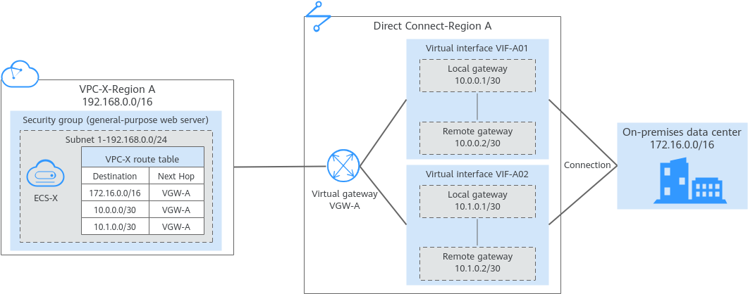
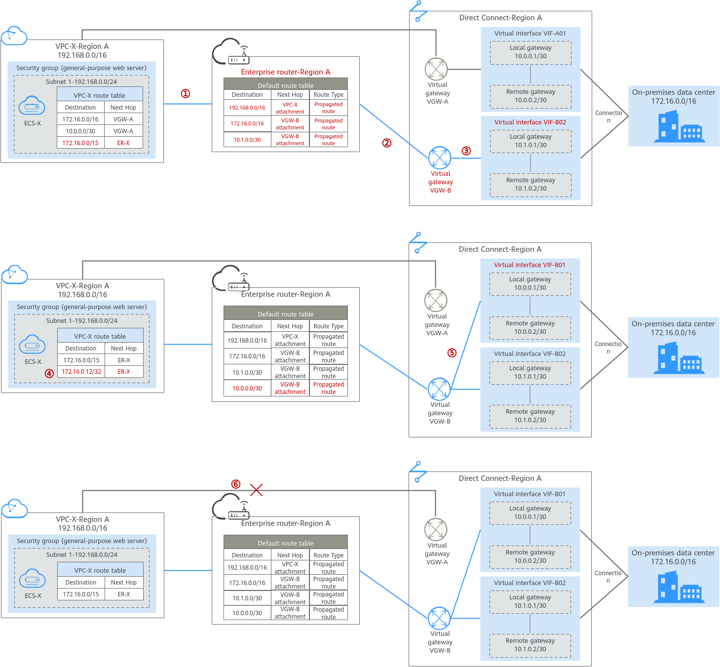
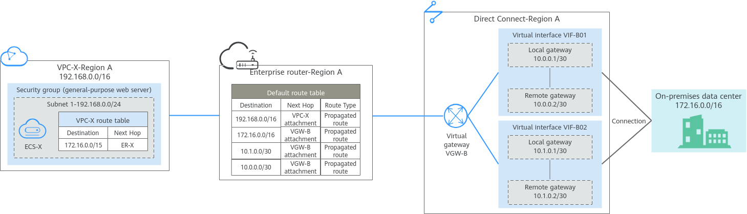
The following figures show the networking in different phases.

The routes in the figures are only examples for your reference. You need to plan routes based on actual service requirements.

Figure 1 Networking topology before the migration
Figure 2 Networking topology during the migration
Figure 3 Networking topology after the migration
Table 1 Overall planning for migrating the network from Direct Connect to Enterprise Router

Route Table

Description

VPC route table

Table 2 lists the routes in this route table.
  1. Before the migration, the VPC route table contains three routes pointing to the on-premises CIDR block and IP address ranges of the local and remote gateways over the virtual gateway.

    In this example, the CIDR block is 172.16.0.0/16, and the IP address ranges are 10.0.0.0/30 and 10.1.0.0/30.

  2. During the migration, to prevent route conflicts, you need to add two routes in the VPC route table.
    1. A route with destination set to a larger CIDR block and next hop to the enterprise router is used for communications between the VPC and the enterprise router.

      The route destination must contain the on-premises CIDR block and cannot be used by other services. In this example, the destination is 172.16.0.0/15, which is larger than 172.16.0.0/16.

      NOTICE:

      The route with destination set to a larger CIDR block must contain the on-premises CIDR block. If one larger CIDR block cannot contain the on-premises CIDR block, you can configure more larger CIDR blocks.

    2. A route pointing to the enterprise router is used to verify communications between the on-premises data center and VPC. The route can be deleted after the verification.

      The route destination can be the IP address of any on-premises server. In this example, the destination is 172.16.0.12/32.

  3. When you delete the original virtual interfaces and virtual gateway during or after the migration, the routes related to the virtual gateway are also deleted.
    In this example, routes with destinations set to 172.16.0.0/16, 10.0.0.0/30, and 10.1.0.0/30 are deleted.
    NOTICE:

    After the migration, you can continue to use the routes with a destination of the larger CIDR block or add routes with destinations that are the same as those of the original routes and then delete the routes with the destination of the larger CIDR block.

Enterprise router route table

Table 3 lists the routes in this route table.

During the migration, add routes pointing to the VPC CIDR block and virtual gateway to forward the traffic between the VPC and Direct Connect connection through the enterprise router.

If Default Route Table Association and Default Route Table Propagation are enabled for the enterprise router, routes with destinations set to the attachments are automatically added when you attach the VPC and virtual gateways to the enterprise router.
  • In this example, when you attach the VPC to the enterprise router, there will be a propagated route destined for 192.168.0.0/16.
  • In this example, when you attach the virtual gateway to the enterprise router, there will be three propagated routes destinations set to 172.16.0.0/16, 10.0.0.0/30, and 10.1.0.0/30.
Table 2 VPC route table details

VPC

Route Table

Destination

Next Hop Type

Next Hop

Route Type

Description

Phase

VPC-X

rtb-vpc-X

172.16.0.0/16

Virtual gateway

vgw-A

System

Destined for the on-premises CIDR block

  • Before migration
  • During migration

10.0.0.0/30

Virtual gateway

vgw-A

System

Destined for the local and remote gateways of VIF-A01.

  • Before migration
  • During migration

10.1.0.0/30

Virtual gateway

vgw-A

System

Destined for the local and remote gateways of VIF-A02.

  • Before migration
  • During migration

172.16.0.0/15

Enterprise router

ER-X

Custom

Destined for the larger CIDR block

  • During migration
  • After migration

172.16.0.12/32

Enterprise router

ER-X

Custom

Destined for any on-premises server to verify communications

During migration

Table 3 Details of the enterprise router route table

Enterprise Router

Route Table

Destination

Next Hop

Attached Resource

Route Type

Description

Phase

ER-X

defaultRouteTable

192.168.0.0/16

er-attach-VPC-X

VPC-X

Propagated route

Destination: VPC-X

  • During migration
  • After migration

172.16.0.0/16

er-attach-VGW-B

VGW-B

Propagated

Destination: on-premises CIDR block

  • During migration
  • After migration

10.0.0.0/30

er-attach-VGW-B

VGW-B

Propagated

Destination: local and remote gateways of VIF-B01

  • During migration
  • After migration

10.1.0.0/30

er-attach-VGW-B

VGW-B

Propagated route

Destination: local and remote gateways of VIF-B02.

  • During migration
  • After migration

Resource Planning

During the migration, you need to create the required number of enterprise routers, virtual gateways, and virtual interfaces. After the migration is complete, the original resources can be released. Table 4 describes the required resources.

The following resource planning details are only examples for your reference. You need to plan resources based on actual service requirements.

Table 4 Resources planning for migrating the network from Direct Connect to Enterprise Router

Resource

Quantity

Description

Phase

VPC

1

A VPC for running your services.
  • VPC name: In this example, VPC-X is used.
  • IPv4 CIDR block: The VPC CIDR block must be different from the on-premises CIDR block. In this example, the VPC CIDR block is 192.168.0.0/16.
  • Subnet name: subnet-X01 is used in this example.
  • Subnet IPv4 CIDR block: The subnet CIDR block cannot overlap with the on-premises CIDR block. In this example, the subnet CIDR block is 192.168.0.0/24.
  • Before migration
  • During migration
  • After migration

Direct Connect connection

1

One connection

  • Before migration
  • During migration
  • After migration

2

The virtual gateway connected to the VPC.
  • Name: In this example, set it to VGW-A.
  • Associate With: Select VPC. The virtual gateway is connected to the VPC.
  • VPC: Select the service VPC. In this example, select VPC-X.
  • BGP ASN: In this example, set it to 64512.
  • Before migration
  • During migration
The virtual gateway used to replace VGW-A.
  • Name: Set it based on site requirements. In this example, VGW-B is used.
  • Associate With: Select Enterprise Router.
  • Enterprise Router: Select your enterprise router. In this example, ER-X is used.
  • BGP ASN: Set it based on site requirements. In this example, the ASN is 64512.
  • During migration
  • After migration

4

The virtual interfaces before the migration.
  • Name: In this example, the two virtual interfaces are VIF-A01 and VIF-A02.
  • Virtual Gateway: In this example, the virtual gateway associated with the two virtual interfaces is VGW-A.
  • Local Gateway: In this example, the local gateway IP address range for virtual interface VIF-A01 is 10.0.0.1/30, and that for VIF-A02 is 10.1.0.1/30.
  • Remote Gateway: In this example, the remote gateway IP address range for virtual interface VIF-A01 is 10.0.0.2/30, and that for VIF-A02 is 10.1.0.2/30.
  • Remote Subnet: In this example, the on-premises CIDR block is 172.16.0.0/16.
  • Routing Mode: Select BGP.
  • BGP ASN: ASN of the on-premises data center, which must be different from the ASN of the virtual gateway on the cloud. In this example, 65525 is used.
  • Before migration
  • During migration
The virtual interfaces after the migration. They are used to replace VIF-A01 and VIF-A02.
  • Name: Set it based on site requirements. In this example, the two virtual interfaces are named VIF-B01 and VIF-B02.
  • Virtual Gateway: Set it based on site requirements. In this example, the virtual gateway associated with the two virtual interfaces is VGW-B.
  • Local Gateway: Set it the same as that of the virtual interface before the migration. In this example, the local gateway for VIF-B01 is 10.0.0.1/30, and that for VIF-B02 is 10.1.0.1/30.
  • Remote Gateway: Set it the same as that of the virtual interface before the migration. In this example, the remote gateway for VIF-B01 is 10.0.0.2/30, and that for VIF-B02 is 10.1.0.2/30.
  • Remote Subnet: In this example, the on-premises CIDR block is 172.16.0.0/16.
  • Routing Mode: Select BGP.
  • BGP ASN: ASN of the on-premises data center, which must be different from the ASN of the virtual gateway on the cloud. In this example, 65525 is used.
  • During migration
  • After migration

Enterprise Router

1

The enterprise router that is in the same region as the service VPC.

  • Name: Set it based on site requirements. In this example, ER-X is used.
  • ASN: Set an ASN that is different from that of the on-premises data center. In this example, the ASN is 64512.
  • Default Route Table Association: Enable
  • Default Route Table Propagation: Enable
  • Auto Accept Shared Attachments: Set it based on site requirements. In this example, enable this option.
  • Two attachments on the enterprise router:
    • VPC attachment: er-attach-VPC-X
    • Virtual gateway attachment: er-attach-VGW-B
NOTICE:

Do not enable Auto Add Routes when you create the VPC attachment.

If this option is enabled, Enterprise Router automatically adds routes (with this enterprise router as the next hop and 10.0.0.0/8, 172.16.0.0/12, and 192.168.0.0/16 as the destinations) to all route tables of the VPC. During the migration, manually add routes with destinations set to the larger CIDR block in the VPC route table.

  • During migration
  • After migration

ECS

1

An ECS used to verify connectivity.

  • ECS Name: Set it based on site requirements. In this example, ecs-X is used.
  • Image: Select an image based on site requirements. In this example, a public image (CentOS 8.2 64bit) is used.
  • Network
    • VPC: Select the service VPC. In this example, select VPC-X.
    • Subnet: Select the subnet that communicates with the on-premises data center. In this example, the subnet is subnet-X01.
  • Security Group: Select a security group based on site requirements. In this example, the security group uses a general-purpose web server template and its name is sg-demo.
  • Private IP address: 192.168.0.137
  • Before migration
  • During migration
  • After migration